Greetings friends, I hope you are well! 🙂
I'm in the "roll up your sleeves and get to work" phase for the Duelund-Corona 832A Project.

Altec Corona 832A loudspeaker.
I'm also trying to be mindful of what I write as being a useful guide to the steps one goes through for building crossovers, so you can use what I write as a template for your own crossover projects.
Eventually, I'll weave all these project articles into one article, which I'll publish at Positive Feedback as a feature article about the Duelund-Corona 832A Project.
The first step to a crossover project is mental preparation. I can hear you laughing now, but really, taking your loudspeakers apart, rewiring them internally, and then building & testing new crossovers can be kind of scary and intimidating if you've never done that before. It was for me.
I want to encourage you that you are capable of accomplishing building a pair of crossovers, and know that your efforts will be rewarded with much better performance from your loudspeakers.
In fact, I think most of you will be shocked at how good your loudspeakers can be once they're equipped with top-notch crossovers.
If you are really concerned about your ability to build crossovers, or just don't have the time to work through a project, you can commission someone to build your crossovers for you, like Pete Riggle (Pete Riggle Audio Engineering).
Having said that, I encourage you to give it a go yourself. You can do it, and the experience you gain will make you fearless for engaging in future audio adventures!
What's next in planning our project?
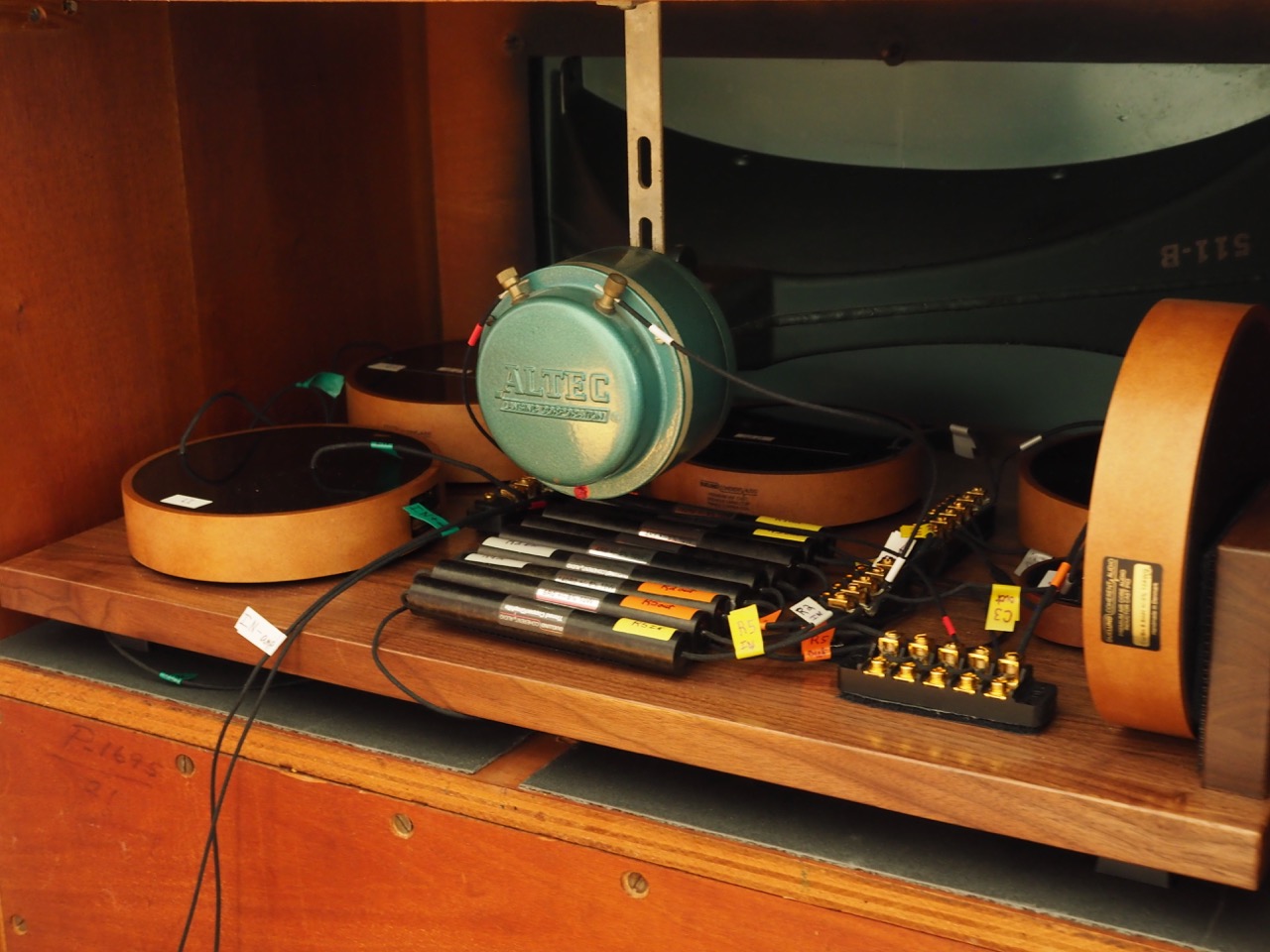
First, I like to take a look inside the loudspeakers to see what I'll be dealing with.
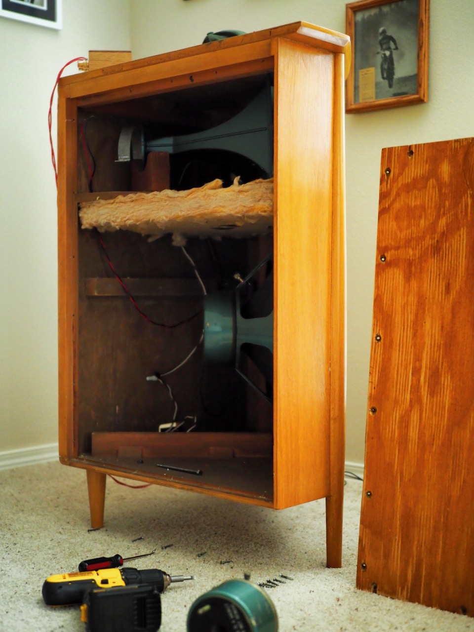
Inside the vintage Altec 832A Corona loudspeakers.
My Coronas are knocking on the door of seventy years old, and given Altec used all kinds of different types of components - cabinets, drivers, crossovers, wiring, etc., - to build their loudspeakers product lines, I wanted to know exactly what were in mine component-wise.
The components complement of my Coronas were the 16Ω 803A bass drivers (built 1947-1958), 16Ω 802D compression drivers (built 1957-1972), 811B HF horns, and N800E crossovers.
The cabinets of my beloved Coronas are a bit grungy looking inside after almost seven decades of service, so one of my tasks will be to clean them up inside. How does that dust manage to get through the grill cloth to inside the cabinets? Sigh.
With vintage Altec loudspeakers it is important to know if the drivers are 16Ω or 8Ω.
For example, for the Hiraga-circuit inspired crossovers I built for my Altec A5s & A7s, whether they are 16Ω or 8Ω drivers determines the values of the inductors & capacitors you will need for the crossover circuit, so you need to know which drivers you have.
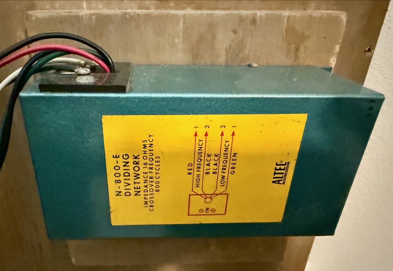
Altec N800E crossover in the Corona 832A.
My Coronas have Altec N800E crossovers, which are designed for 16 ohm drivers.
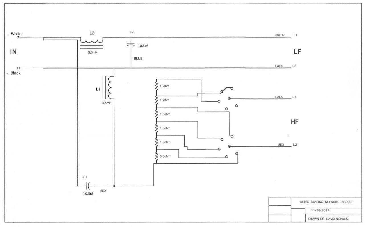
N800E crossover schematic courtesy of Great Plains Audio.
The next step is to get a copy of the crossover schematic so you can figure out what circuit components to order (above).
In my case I wanted to do something different from the stock Altec adjustable resistor network in the HF circuit that provides attenuation for the 802D compression driver.
I wish that all loudspeakers included the ability to attenuate the HF output. That ability makes it much easier to accommodate the voicing of different amplifiers, rooms, speaker positioning, listener positioning, and ears. 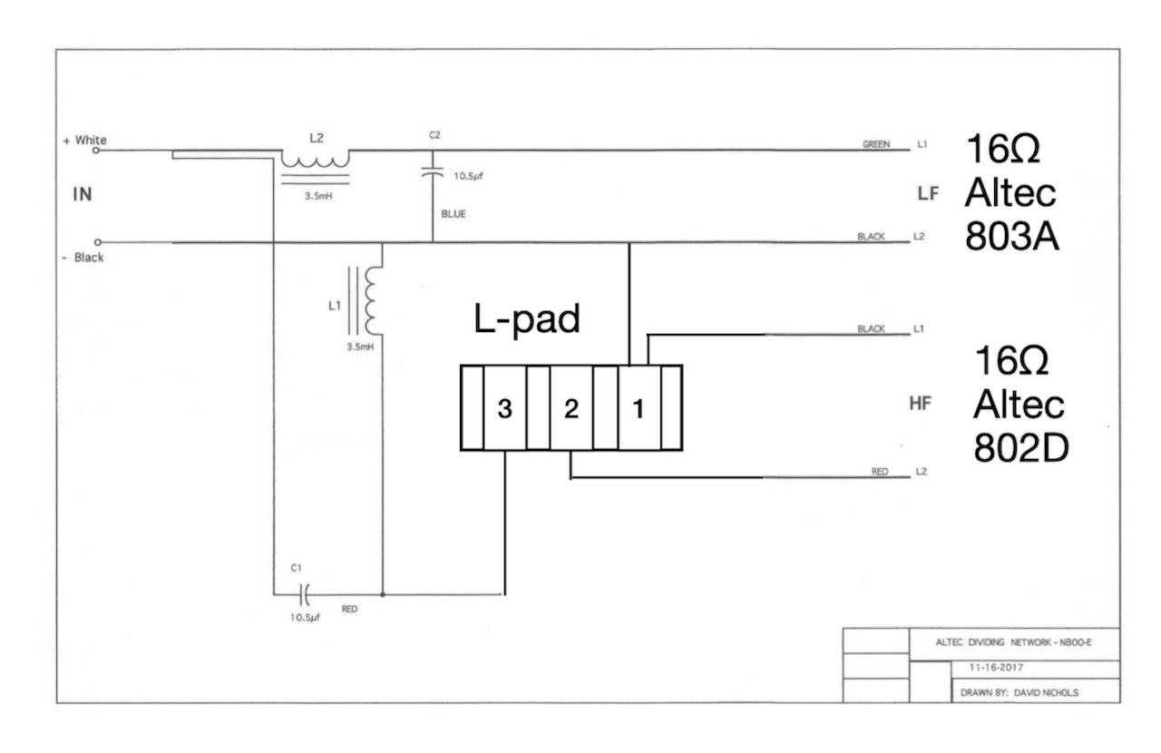
N800E crossover with L-pad replacing the resistance network.
I've already written about arriving at the circuit above, where an L-pad replaces the HF resistance network for my Coronas HERE, so you can check that out for more information.
If your loudspeakers are current production items, try contacting the manufacturer to get a copy of the crossover schematic.
Generally manufacturers are happy to provide a crossover schematic to their customers, but sometimes they won't. So you'll need to look elsewhere for a schematic if that is the case, or buy loudspeakers from a manufacturer that is more inclined to help you in your audio adventures.
In looking at the N800E crossover schematic I see that I would need four 3.5mH inductors and four 10.5uF capacitors for a pair of crossovers.
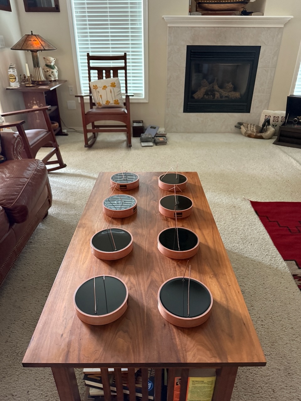
Duelund CAST copper 3.5mH inductors and 10.5uF capacitors.
The main idea for building a new pair of crossovers for your loudspeakers is to use higher-performing components, as generally crossover components are chosen for a particular price point. Often those components are average in their performance because of cost constraints in manufacturing, so better performance can easily be achieved with better components.
If you want to get the performance out of your loudspeakers that they are truly capable of, build crossovers with better components in their circuits.
You will want to choose components that let as much information through as possible, like the Duelund CAST components I've used in most of my crossover projects.
I can tell you from experience, in comparing different capacitors in my Westminster Royale SE crossovers, the Altec A5 Voice of the Theatre crossovers, and the Stokowski Altec A7 crossovers, the difference in the quality of components on performance is huge.
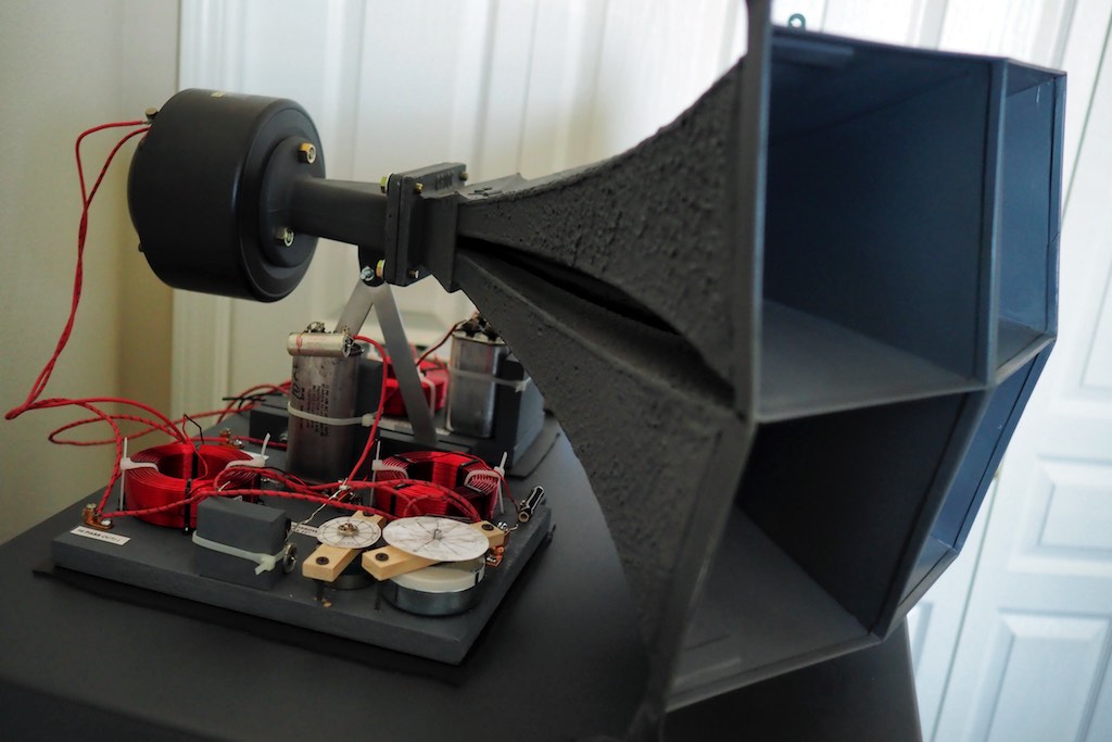
HIraga-san inspired crossovers of my vintage Altec A5s.
For example, for my A5s' Hiraga-inspired crossover circuits I did a typical crossover build with average component parts, and for my Stokowski Altecs I built Hiraga-style crossovers with the über Duelund CAST tinned-copper components.
Duelund CAST tinned-copper crossovers in the "Stokowski" Altecs. loudspeakers.
The difference in performance was huge between these two Hiraga-inspired crossover circuits. With the average Hiraga build it was like someone threw quilts over the loudspeakers compared to the Duelund CAST Hiraga build.
There's just less of everything coming through with your average OEM components.
The Duelund components let so much more musical information come through that it is kind of shocking when you first hear them. The second thing I noticed was how much more musically natural the music sounded.
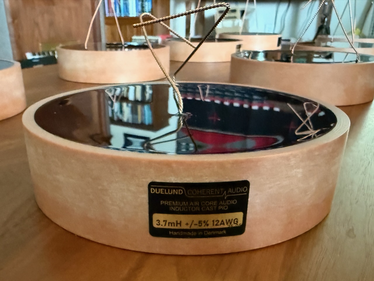
Closeup of a Duelund CAST 12AWG pure copper 3.7mH inductor.
With really good components in your crossover circuits, performance increases by leaps and bounds, so go for the best components that you can fit into your project budget.
N800E crossover with L-pad replacing the resistance network.
Take a look at the schematic above. The first circuit component we come to in the low-frequency part of the circuit is the 3.5mH inductor, followed by a 10.5uF capacitor.
The inductor and capacitor are used to filter the frequency range that is sent to the Altec 803A low-frequency driver. Ditto for the high-frequency part of the circuit, where the inductor and capacitor filter the frequency range that is sent to the Altec 802D compression driver.
For those who would like to learn more about how crossovers function, check out this article at the SoundCertified website HERE.
The 3.5 mH Duelund CAST copper air core inductors are used in the L2 (LF) and L1 (HF) positions in the crossover circuit.
Now let me tell you a little more about the construction of the Duelund CAST copper air core inductors we are using in the Duelund-Corona 832A Project.
Inductors are passive devices that store energy in their magnetic field.
The Duelund CAST air core inductor - as the name implies - utilizes an air core, where pure annealed soft copper foil in natural paper and oil is wrapped around the core (instead of around a magnetic core as with many inductors). So an inductor is one foil coiled up to create the desired amount of inductance.
Here's how Duelund CAST air core inductors are made: foils of pure copper or silver are initially wound with paper around an air core to a certain value of inductance that is greater than the needed inductance.
Then the coiled foil is put under vacuum pressure in an oil tank at high temperature for about a week to permeate everything with oil. Then the foil is coiled by hand in a humidity and temperature-controlled room to an exact inductance specification, and then it is placed back into the oil.
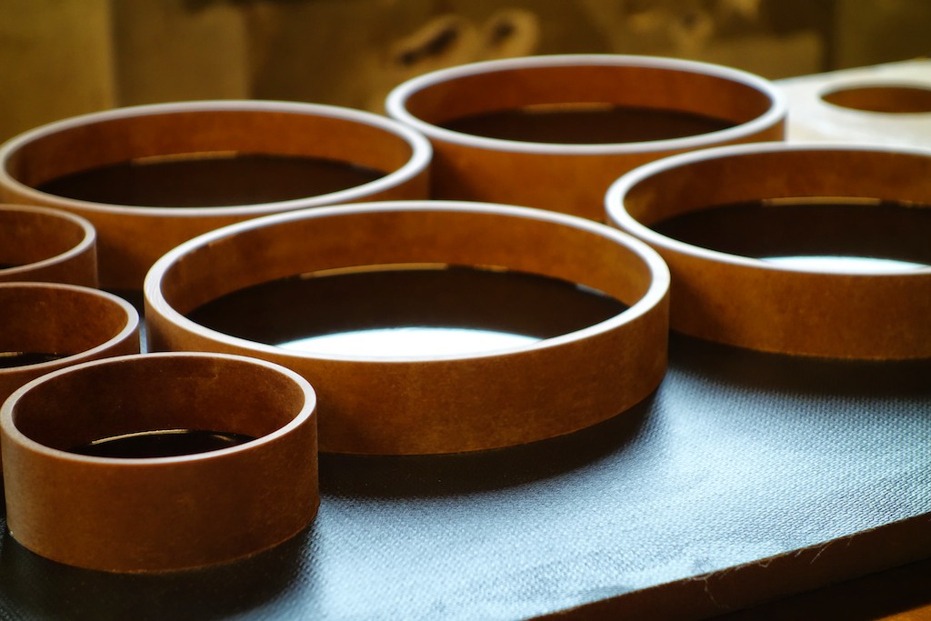
Immediately after this the winding is sealed with a special lacquer that takes a week to cure. During this process a ring of vacuum impregnated paper (above) has been readied with a base of CAST material (below).
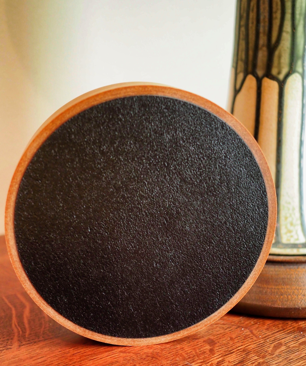
Base of Duelund CAST air core inductor.
The coiled foil is then heated and placed in the ring & base assembly and CAST material is poured on top of it in five stages.
A precisely controlled flame is then quickly applied over the surface to drive any air bubbles out of the CAST material. Following this step the inductor is measured and checked against controls to ensure quality.
The total production time is typically six to eight weeks to make an inductor.
Closeup of a Duelund CAST 12AWG pure copper inductor.
Ok, that's all for now. As always, thanks for stopping by, and may the tone be with you! 🙂
Previous Articles In This Series
- A New Audio DIY Project Announcement: The Duelund-Corona 832A Project! HERE.
- Today's Fresh Catch: Capacitors & Inductors for the Duelund-Corona 832A Project! HERE.
- The Duelund-Corona 832A Project: The resistance network! HERE.