
Detailed Description of the 2-Stage Power Amplifiers:
Parts List & Design/Construction Notes for the Bruce Berman 45-300B SE DHT Amplifier
Rev. A, of March 19, 2022
Design & Construction Notes, & Listening Impressions
My amplifier design borrows heavily from that espoused by the late Sakuma-San, and he deserves much credit for the work he had done in developing and promoting this truly novel type of audio amplifier. His philosophy in all things related to audio was largely first recognized here in the West in the late 1990s, by virtue of an article that appeared in Sound Practices, issue no. 13.
Although my amplifiers utilize the WE-300B as the preferred output tube, other directly-heated tubes may be easily substituted, including a 45, a triode-connected 46, or the 50, 2A3, VT-52, etc.
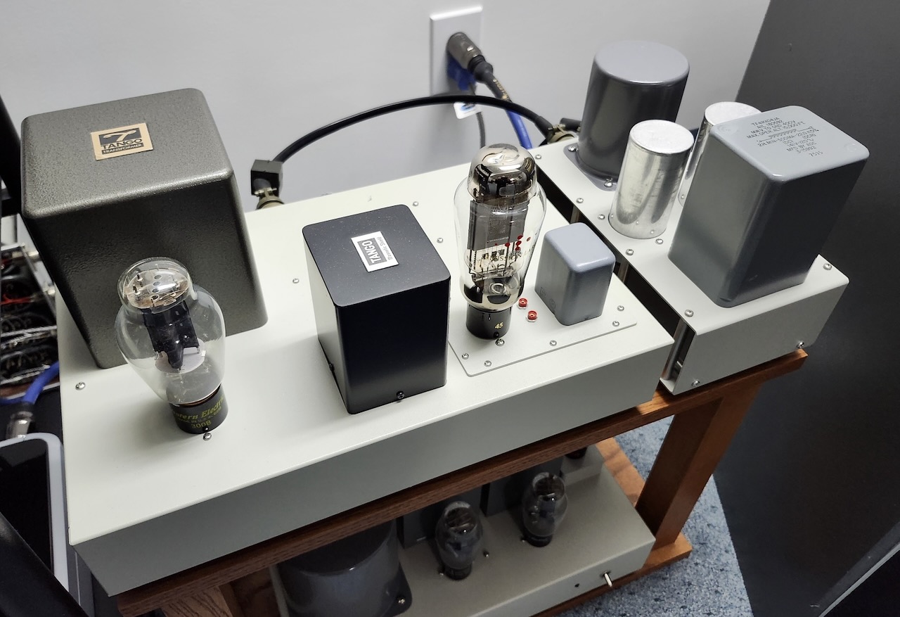
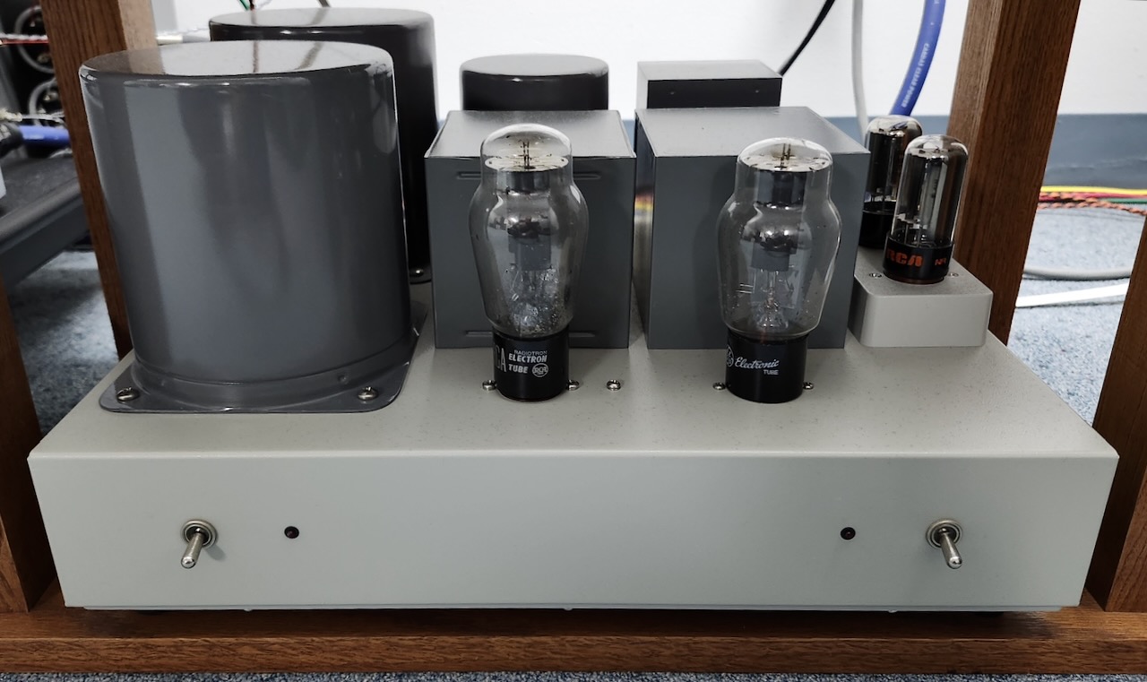
Top view of the power amplifier and external LC power supply chassis.
The builder will have to make the appropriate changes to the filament and plate voltages, as well as the cathode bias resistor if any of these other tubes are employed. The output transformer (OPT) remains unchanged, although when using a 2A3, an OPT having a primary impedance of 3500 ohms may be desirable, to maximize the available output power.
My preference would be to retain the use of the 45 as the driver stage tube.
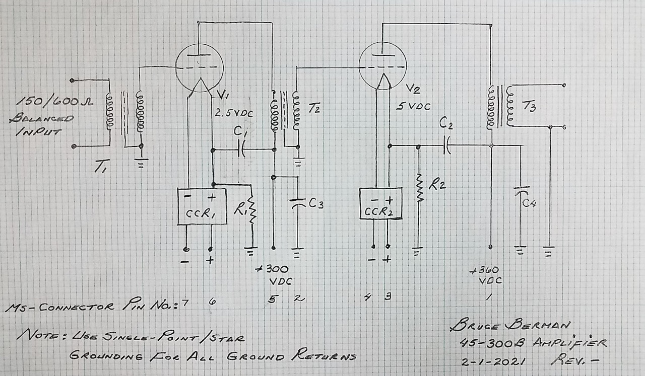
Bruce Berman 45-300B amplifier circuit.
My schematic drawings for my 2-stage transformer-coupled 45/WE-300B power amplifier (above), and its mating power supply unit (below), are primitive hand-drawn quality, as I haven't had access to CAD since I retired.
If someone wants to recreate these two schematics in CAD and provide them to me, I would be thrilled!
As this circuit and signal path are so simple, the quality of each of the components will have a significant impact as to the overall quality of the reproduction. This is particularly true for all of the audio transformers and capacitors (C1 and C2) which are within the signal path, and will largely dominate the sonic characteristics of the amplifier. Substitutions of these parts should be very carefully considered and auditioned with regard to their potential sonic impact.
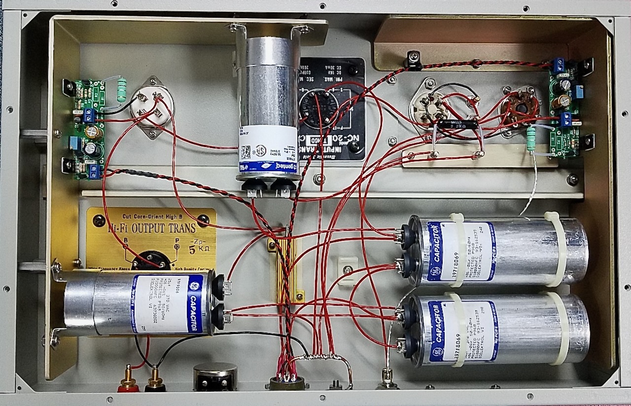
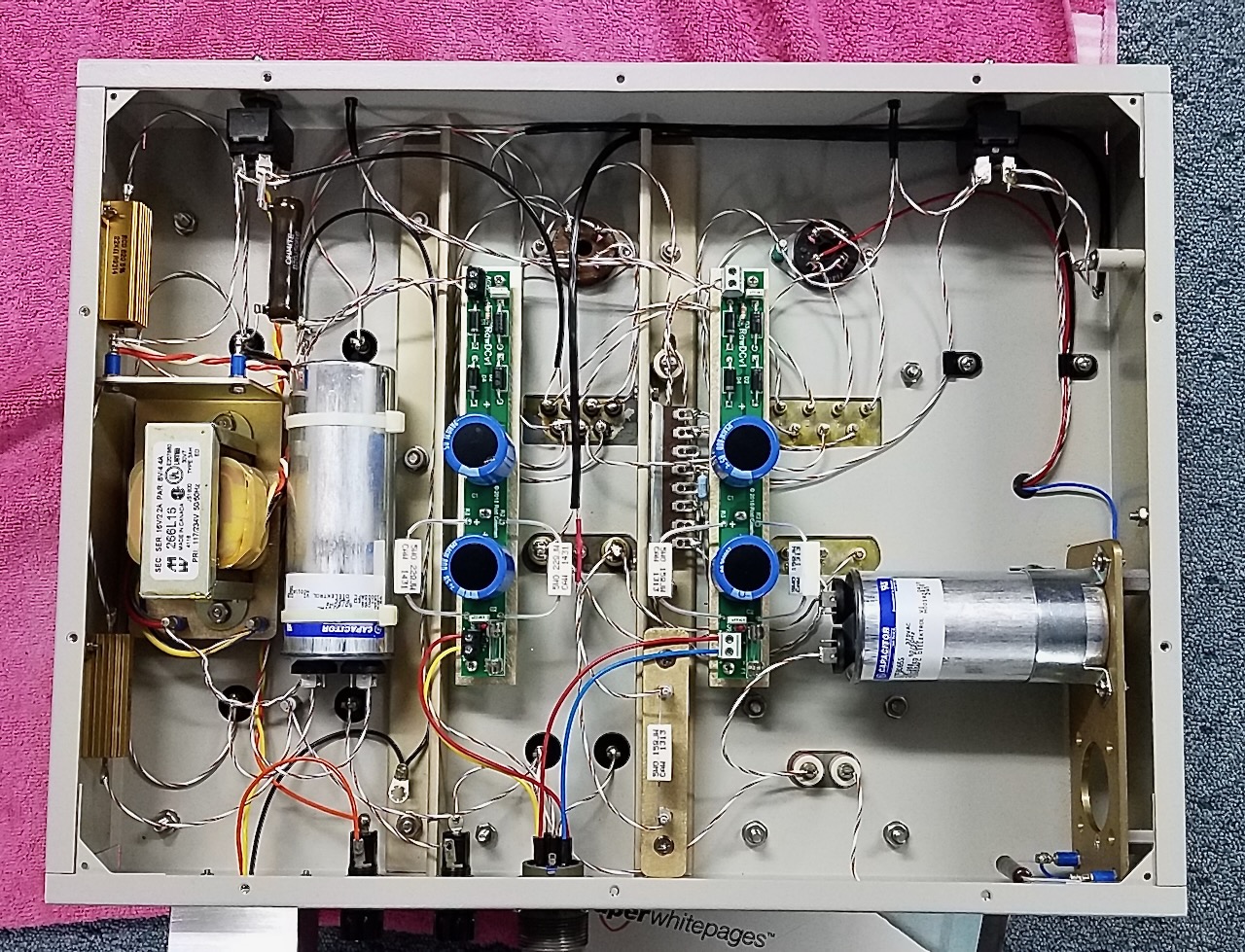
Under-the-hood view of the 2-stage transformer-coupled power amplifier chassis.
Additional notes about the under-the-hood view photo above:
Excuse the messy layout here, as this amplifier has also been modified more times than I care to remember over the years. The multitude of wiring is mostly for the star grounding. I'd now use a single heavy copper bus with all of the component grounds returning to it, and I'd do the entire layout completely differently if I had to do it again. All wiring is Kimber copper, with the exception of the short section of Kimber silver KCAG for the audio input line.
Note the two large 1/8"-thick aluminum heat sinks for the Coleman constant-current regulators used for DC heating of the 45 and WE-300B filaments. As the interior of the chassis is painted, I could not easily heat-sink the regulators directly to the chassis, necessitating the use of these large homebrew heat sinks.
The now-superfluous wire-wound potentiometer on the rear of the chassis was for the hum nulling adjustment, when I was using AC heating for the WE-300B.
Back to the description:
The use of output transformer T3 with a primary impedance of 5000 ohms is critical to achieving the lowest possible 3rd harmonic distortion products from the 300B output stage. If the primary impedance of T3 is changed to the more common 3000-3500 ohms, the 3rd harmonic distortion performance will degrade by approximately 6 dB, but the audio output power will be somewhat increased. A 5000 ohm primary impedance for T3 is therefore strongly recommended for optimum sonic performance of this amplifier, and the Western Electric published 2nd and 3rd harmonic distortion data for the WE-300B makes this very clear. The truly magnificent-sounding Tango Type X-5S is long discontinued, but the ISO Type FC-40-5S is the exact replacement for the X-5S. George Lenz of Tubes USA has advised that ISO acquired Tango a number of years ago, and their technical and build quality is equal to that of the Tangos. The ISO FC-40-5S is the replacement part number for the Tango X-5S.
As the circuit utilizes the so-called Western Electric “Ultra-Path” topology, the high voltage power supply ripple must be reduced to the absolute minimum. The Ultra-Path configuration eliminates the sonic degradation incurred by the use of cathode bypass capacitors, which would otherwise be required in this transformer-coupled, self-bias circuit, but it does couple any power supply ripple directly into the cathode of each tube, where the ripple is amplified by the amplification factor (u) + 1 of each of the tubes. A separate 3-section choke input filter will be required for the 45 driver and 300B output stage power supplies, per the power supply schematic. This LC-LC-LC filter arrangement will eliminate any audible power supply hum when the amplifier is used with the most sensitive loudspeakers. Be sure to use filter chokes for the 300B and 45 plate supplies of at least 110 Ma current rating; this will serve to minimize the DCR of the filter chokes, and reduce the overall source impedance of each of these power supplies. Note that the DCR of these filter chokes (L1-L6) as specified in the Power Supply Parts List are fairly critical, as they and the other component values in each of the HV power supply sections define the correct plate voltages required under load for the 300B and 45 stages.
I have found that the 25 uF and 50 uF GE 97F-series polypropylene and oil capacitors I have specified provide better sonic quality than the more commonly available ASC polypropylene and oil motor run capacitors, and the use of these specific GE capacitors is very much encouraged.
Based upon the information contained herein, an experienced audio amplifier builder should be able to easily design a suitable power supply per the attached schematic and parts list for use with the Bruce Berman 45-300B Amplifier. Remember, each amplifier will require a separate plate supply for the 45 driver stage; a separate plate supply for the 300B output stage; and two separate raw DC supplies for the Rod Coleman filament constant current regulators, with one raw DC supply allocated to the 45 constant current DC filament regulator, and the other raw DC supply allocated to the 300B constant current DC filament regulator.
Line-to-grid input transformer T1 provides the required voltage gain in this circuit, which is around 20 dB. The Peerless Type 4665 or the Peerless K-241-D are recommended for their superior sonics and performance specifications, but these transformers are now scarce and expensive. The Altec-Lansing Type 15095 line-to-grid input transformer is very common, reasonably priced, and will provide excellent performance, with approximately a 6 dB reduction in overall gain due to its secondary impedance being only 15,000 ohms, whereas the secondary impedance of the Peerless 4665 or K-241-D is 70,000/84,000 ohms. Many systems can handle a 6 dB reduction in amplifier gain, but this is of course completely system dependent. The Peerless 4665 and K-241-D do have audibly better sonics, but the trade-off here will be price and availability of this superb quality transformer. I don’t think anyone will be disappointed if they elect to use the Altec-Lansing 15095, but the use of the Peerless 4665 or K-241-D are very much encouraged.
When the Altec-Lansing 15095 transformer is used in this circuit, the F1 high frequency response will be somewhat extended when compared to the Peerless 4665 or K-241-D, due to the Miller Effect capacitance presented by the 45 driver tube and the 15K ohm secondary impedance of the input transformer, but the input transformer audio bandwidth/frequency response will largely be the dominating factor with regard to the overall frequency response of the amplifier. With the Peerless 4665 or K-241-D, the upper limit to the frequency response will be down approximately -1 dB at 30 Khz.
Although 6 dB of gain will be obtained if the input transformer 150 ohm input impedance is used, this will have a negative impact on the upper frequency limit of the amplifier, again due the Miller capacitance. For this reason, use only the 600 ohm primary tap to take advantage of the full amplifier bandwidth that can be obtained.
Other potential candidates for T1 may include the UTC LS-10X, the UTC HA-100X, or any very high-quality line-to-grid input transformer (including Triad and Tamura) capable of operating into an unterminated load impedance, and supporting line-level (0 dBm/6 milliwatt reference) audio. Lundahl also makes a high-quality line-level input transformer, which should work very well in this application, as other builders of my amplifier design will attest.
Note that most microphone input transformers cannot support line-level audio without serious core saturation issues, and the resultant severe distortion. The Peerless 4665, the K-241-D, and the Altec 15095 are specified with a nominal operating level of +8 dBm, and as such, they provide plenty of headroom, and will not saturate when driven by the typical line-level source.
As the input impedance of this amplifier is 600 ohms, a preamplifier or transformer volume control (TVC) capable of easily driving a 600 ohm load is required. The TVC is a superior device for use with this amplifier, even when compared to active preamplifiers using an output transformer, due to its extremely low output impedance. The low output impedance of the TVC is reflected to the grid of the 45 input stage through the input transformer, and this will result in a reduction in the Miller capacitance presented by the 45, and as noted earlier, a higher upper limit to the frequency response of the amplifier. It’s use, therefore, is highly recommended.
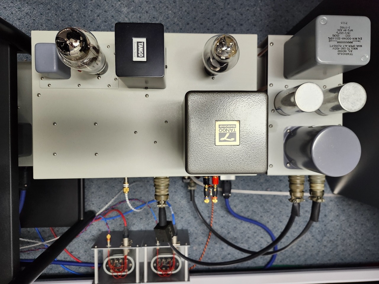
Top view showing the rear of the power amplifier.
Above is a top view showing the rear of the power amplifier, and the Amphenol MS-connector umbilical interconnecting cables between the amplifier, power supply, and the external LC power supply filter unit. Note that the Belden orange and black twisted pair cable is for connection to my subwoofer L + R channel combining network. Alpha Core silver speaker cables are used for connection to the Altec A-5s.
My fellow audio-maniac and friend Andy Moore has described the use of my amplifiers with an active preamplifier manufactured by the German company Einstein. This very high-quality preamp provides an extremely low output impedance on the order of 50 ohms, also making it ideal for use with this amplifier, and Andy raved about the sonics with this equipment combination.
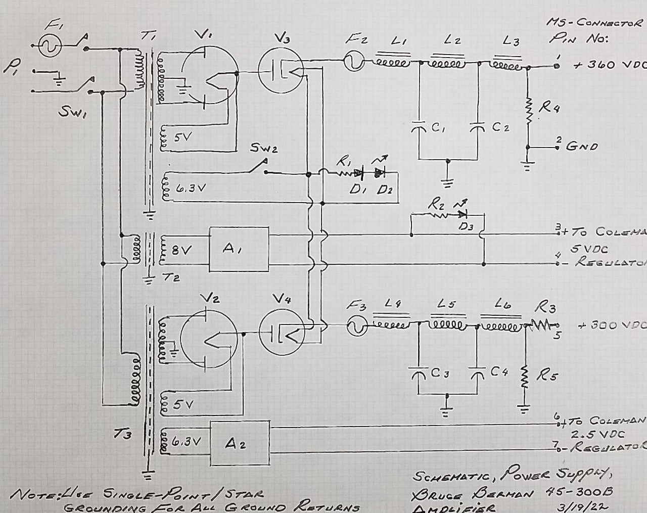
Bruce Berman power supply circuit for 45-300B amplifier.
The parts selection of the power supply will also have a major impact as to the overall sonics of this amplifier. A separate HV plate power supply is required for the 45 driver stage, and a separate HV plate power supply is required for the 300B output stage.
Bruce Berman power supply circuit for 45-300B amplifier.
Mercury vapor rectifiers are required in order to keep the power supply source impedance to the absolute minimum possible, and to achieve the open, fast, and powerful sound this amplifier will provide. I used two type 83 mercury vapor full-wave rectifiers; one for the 45 driver stage plate supply, and one for the 300B output stage plate supply.
A 6AX4GT TV damper diode tube is in series with the rectified DC output of each 83, and this serves to provide a very graceful application of the high voltage to each 83.
45-300B power supply.
To preheat the filaments of the 45, 300B, and the two 83 rectifiers, the first power switch is thrown; this energizes the filaments for these tubes. After waiting approximately 60 seconds, the period required to fully preheat the 83 mercury vapor rectifiers, the second power switch is thrown; this energizes the heaters for the 6AX4GT damper diodes, and the 83s begin conducting as soon as the 6AX4GT series-pass tubes begin conducting.
The 6AX4GT series-pass tubes will also suppress any rectification switching transients from the 83 mercury vapor rectifiers, further improving the purity of the sound. The use of the 6AX4GT series-pass tubes and the Coleman constant current regulators, will provide a very graceful application of the plate and filament voltages to the 45 driver and the 300B output stage, ensuring the longest possible lifetime for these tubes.
Be sure to use the specified 22K ohm at 50 watt chassis-mount bleeder resistors at the output of each high-voltage plate supply section, to improve the voltage regulation, and to discharge the filter capacitors for user-safety concerns.
All of the low-voltage (for the raw DC supplies for the Coleman filament constant current DC regulators), the 83 filaments and the 6AX4GT heaters, and the high-voltage plate supplies should employ the use of transformers with electrostatic shields between the primary and secondary windings, to minimize the capacitive coupling of any noise that may be present on the AC line.
For the lowest noise, the amplifier and the mating power supply unit should be built on two separate chassis. This will most likely be a necessity anyway, as the quantity of the filter chokes and transformers used in the construction of these power supplies is substantial. The use of Amphenol MS-type military standard 7-pin connectors for terminating the umbilical interconnecting cable between the power supply and amplifier chassis is recommended.
Due to the large number of filter chokes, filter capacitors, power transformers, and the low voltage transformers for the raw DC supplies for the Coleman 45 and 300B filament constant current regulators, the power supply unit for each amplifier will necessarily be large and very heavy. Be sure to take this into consideration when dimensioning the size of the chassis, and the thickness of the chassis sheet metal. I recommend an aluminum top plate for the chassis having a thickness of 0.125” to support this heavy load without any flexion. Don’t be surprised if the combined weight of one channel of your Bruce Berman single-ended 45/300B amplifier and power supply unit is around 100 pounds.
A 1 volt RMS input will drive this amplifier to approximately 5.5 to 6.0 watts output.
With the voltages specified in the schematic, the 45 driver tube will draw approximately 25 Ma. of plate current, and the 300B output stage will draw approximately 75 Ma. of plate current. These values will provide optimum levels of linearity and low distortion, and long tube life.
Please click on the link below to go the next page.