
I'm excited by what I'm hearing from my Altec A5 Voice of the Theatre loudspeakers.
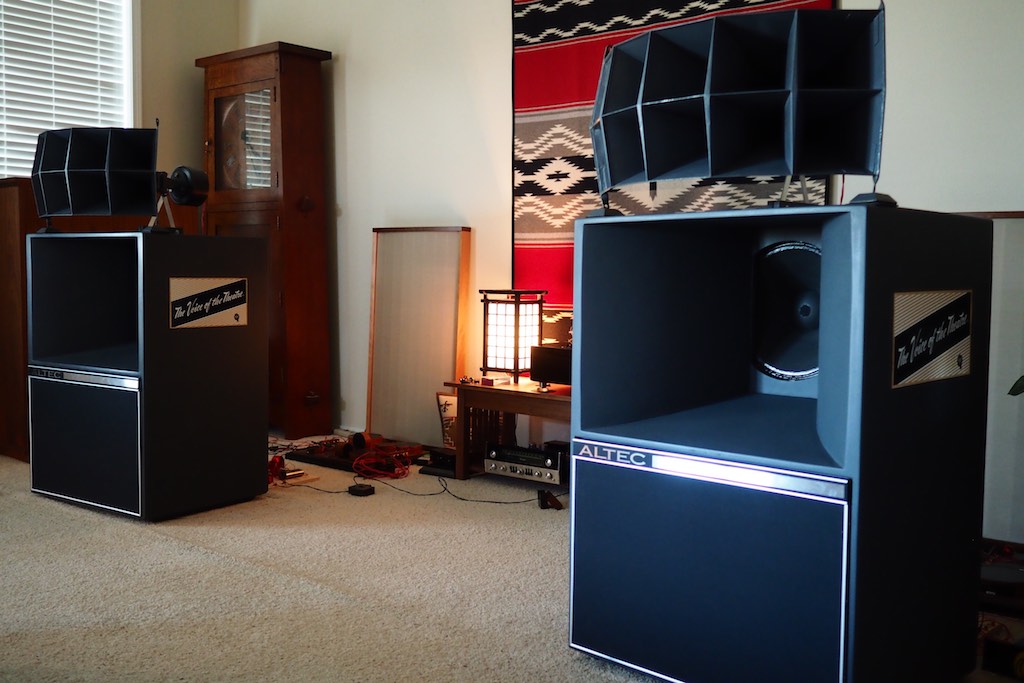
I've made a few modifications to the crossovers I'm building, and to the wiring from the crossovers to the drivers, that really are working great together.
I still have a few experiments I want to try with the crossovers, but I feel like I'm *almost* there. Actually, even if I stopped right now the performance would impress most listeners mightily I think.
Last night on Facebook, I was telling friends:
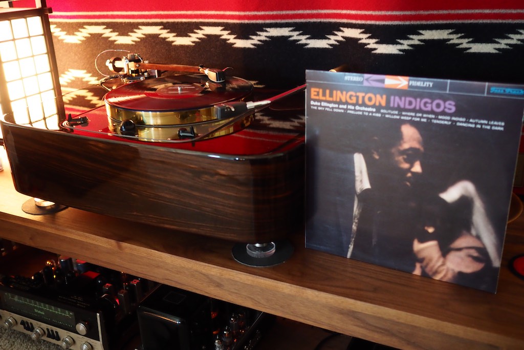
"I'm listening to Ellington Indigos on vinyl right now while I'm dialing in the crossovers on my vintage Altec A5 Voice of the Theatre loudspeakers. It sounds spooky real!"
"Ellington at live-like levels sounds naturally live, and with a sense of dynamic ease that is spellbinding. Good stuff!"
My crossover diagram was getting so marked up with changes that I decided I'd better make a new one for you that would be easier to read (below).
I used some Mac compatible software called Electric Design to draw the crossover circuit and it only costs $17 and works great - a bargain! Mac users can download Electric Design from the Mac App Store.

At the urging of Pete Riggle, I installed a pair of 16 Ohm L-pads (see above) into the high-frequency circuits of the Hiraga-inspired crossovers I built, and it has really helped me to get them dialed in so that high-frequency and low-frequency horns are well-balanced and blending together beautifully.
At Yazaki-san's suggestion, I also have a pair of Clarostat potentiometers (R3-VR in the circuit show above) installed on the high-frequency notch filters at R3 to give me a little adjustability for the depth and shape of the notch filter.
Pete Riggle was so kind as to run some SPICE simulations of the combination of the L-pad and the variable resistor (VR) in the notch filter for various values, and even drew the frequency response plots and labeled them by hand! I must admit to being awed! Thank you, Pete!
Pete: "Attached please find Bode diagrams (frequency response plots) showing the electrical output of the 16 Ohm Hiraga crossover into 16 ohm resistive loads. The assumption is that the tweeter has an L-pad which allows the output of the tweeter to be adjusted relative to the woofer."
"Figures 1, 2, and 3 show the results assuming the tweeter/L-pad combination is set to be 12 dB more sensitive on axis than the woofer."
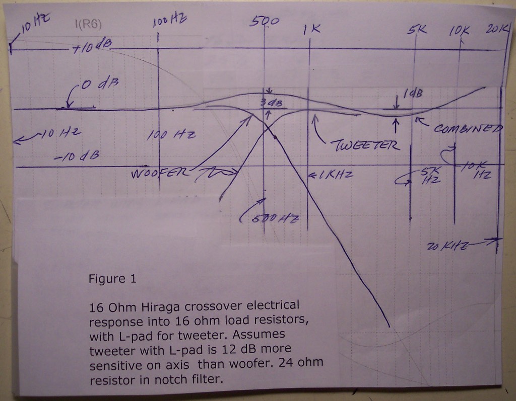
Figure 1
Pete: "Figure 1 has the 24 Ohm value specified by Hiraga for resistor in the notch filter. This give a very nice result, with a 3 dB bump around 500 Hz and a 1 dB dip around 4 kHz."
Jeff: With my A5's, even though the Hiraga 24 Ohm value at R3 for the notch filter measures very nicely, I found it to be overly aggressive in the highs, so I have tried values for R3 between 24 Ohms and 35 Ohms, which makes for much more musical results in my system / room.
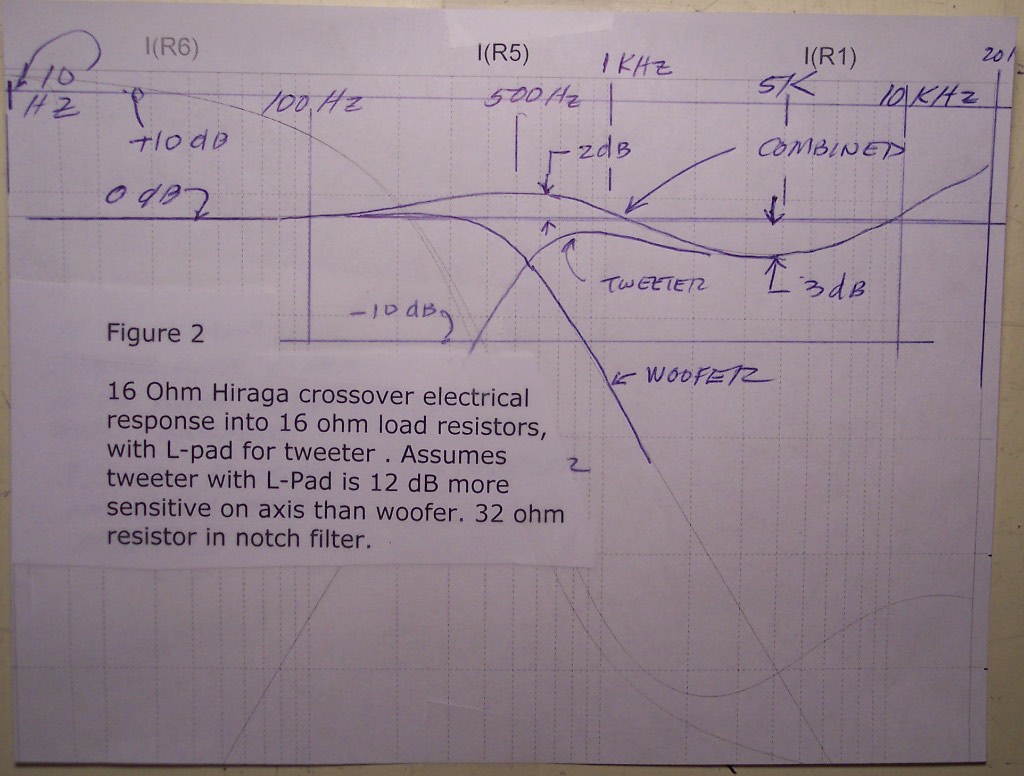
Figure 2
Pete: "Figure 2 has a 32 Ohm value for the notch filter resistor. Note that, relative to the results of Figure 1, this change of resistor value depresses the response output by an additional 1 dB at 500 Hz and 2 dB at 4 kHz, relative to the response shown in Figure 1."
Jeff: Even though Figure 2 shows a 'bumpier' plot, my listening tests have revealed that R3 values between 30 Ohms and 35 Ohms sounds better in the musical sense. At 24 Ohms I cringe at the musicality, and between 30 Ohms and 35 Ohms I smile, while cranking up the volume and grooving out to the music! At the moment my total resistance for R3 is 30 Ohms, and it is sounding very nice.
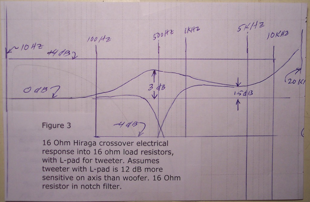
Figure 3
Pete: "Figure 3 has a 16 Ohm value for the notch filter resistor. Comparing the response with that shown in Figure 1, note that with the smaller notch filter resistance value the response still has the 3 dB bump around 500 Hz, that we see in Figure 1, but that the output at 4 kHz has risen 2.5 dB from the response curve of Figure 1. The response curve of Figure 3 has a little misleading because of the expanded vertical scale provided by auto-scaling by Spice."
Jeff: A 24 Ohm resistor in the notch filter (R3) sounds nasty to me, so I can't even imagine going to 16 Ohms! That will be the R3 experiment that I don't try!
Pete: "Figures 4, 5, and 6 show the results with the tweeter shelved 6 dB higher than in Figures 1, 2, and 3. The combination of tweeter and L-pad is set to be 18 dB more sensitive on axis than the woofer."
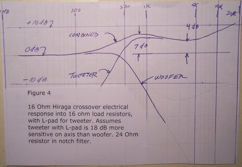
Figure 4
Pete: "Figure 4 shows the results assuming the tweeter with its L-pad set to be 18 dB more sensitive on axis than the woofer. Here we have shelved the tweeter 6 dB higher than in the configurations of Figures 1, 2, and 3. With the 24 Ohm notch filter resistor we see a 7 dB bump in response at 800 Hz, slumping down to a trough at 3.5 kHz, the trough bottoming at 4 dB above the woofer baseline output. As with all these calculations, the tweeter output rises after the trough."
Jeff: The Figure 4 combination would kill me! 😉
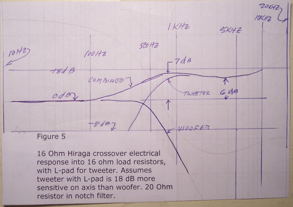
Figure 5
Pete: "Figure 5 is for a configuration like that of Figure 4, but with a 20 ohm resistor in the notch filter. The 7 dB bump in response at 800 Hz remains; but the trough at 3.5 kHz bottoms at 6 dB above the woofer baseline output."
Jeff: Arrrgh!
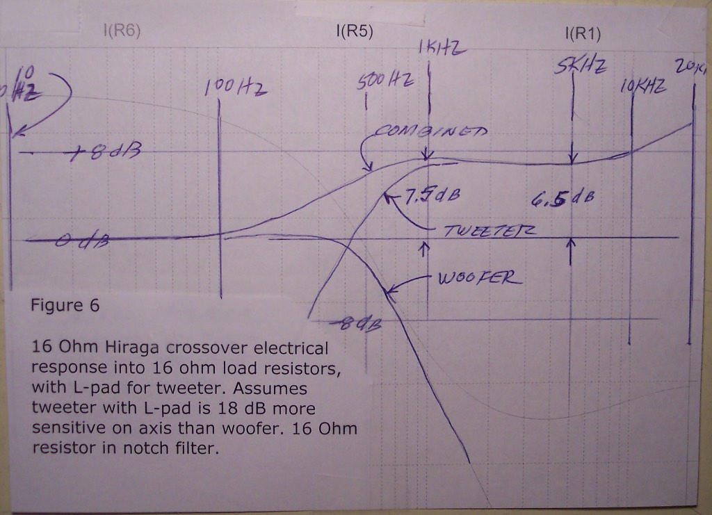
Figure 6
Pete: "Figure 6 is for a configuration like that of Figures 4 and 5, but with a 16 ohm resistor in the notch filter. The bump has now moved to 1 kHz, and increased to 7.5 dB. The trough is now at 4 kHz, where the output is about 7.5 dB above the woofer baseline output."
Jeff: Arrrgh times two!
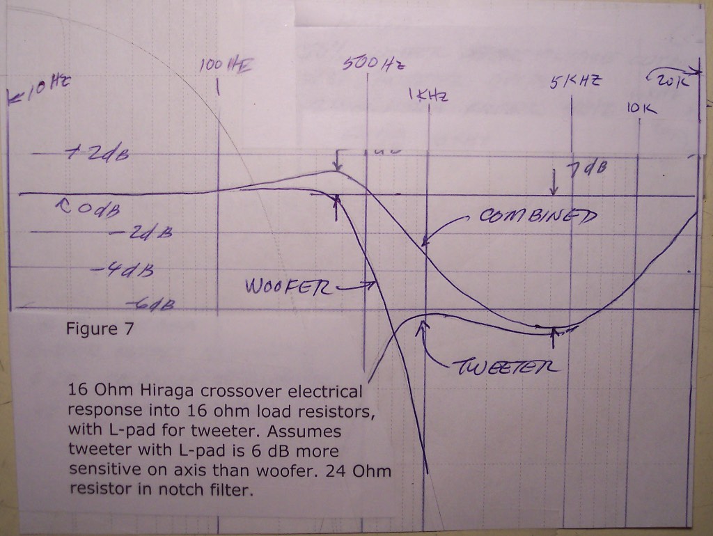
Figure 7
Pete: "Figure 7 gives the result for a case like that of Figure 1, but with the tweeter shelved 6 dB lower. Here the L-pad/tweeter combination has a sensitivity 6 dB above that of the woofer. The notch filter has the 24 ohm resistor. There is a response bump of 1 dB at 400 Hz, and a response trough of 7 dB at 4 kHz. Again, the auto-scaling provided by Spice has given an exaggerated view of the vertical scale."
"One would think that the best sound would be with the settings as used in the configuration which gave Figure 1."
"Of course these figures show only the electrical response of the crossover, with adjustment to show the effects of tweeter/L-pad settings. In the real world there would be small deviations attributable to the electrical impedance characteristics of the drivers with their horns and enclosures, and changes attributable to the on-axis and off axis frequency response characteristics of the drivers. These considerations aside, the Spice results give a pretty good idea of how the crossover itself behaves."
"One thing I would point out here is that it is worth studying the nature of the changes attributable to the L-pad versus those attributable to the notch filter resistance."
"Sometime tomorrow I will email a figure of the Spice model including the metering elements used to get the response curves."
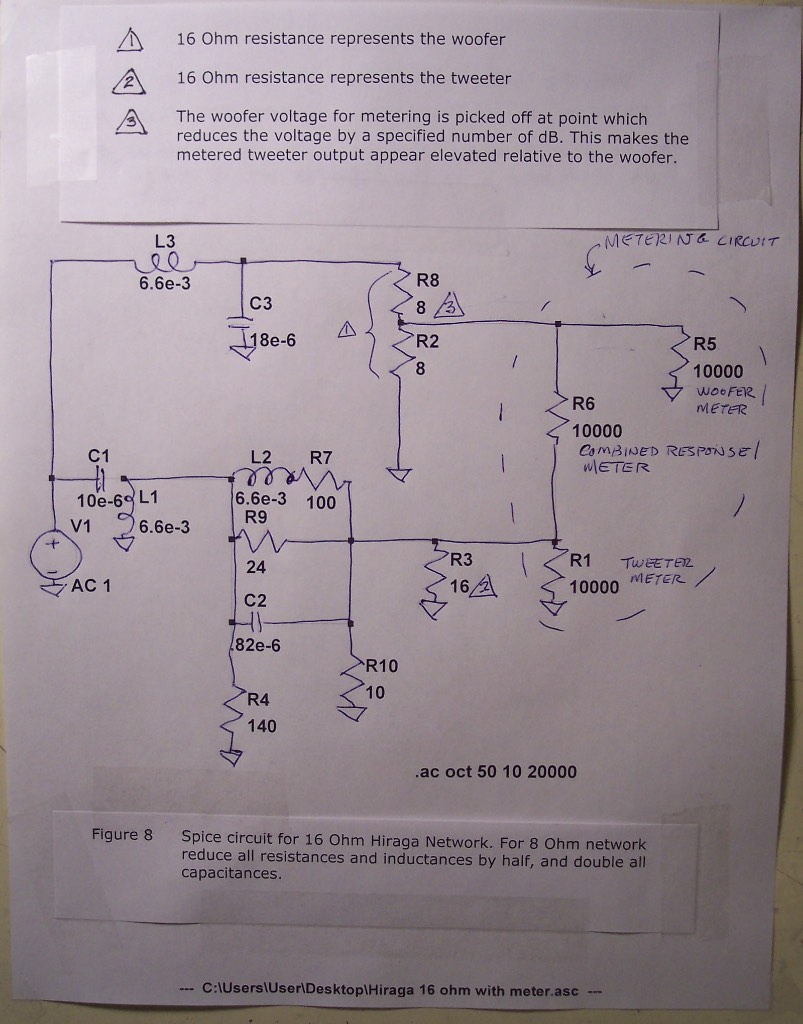
Figure 8
Pete: "Attached is Figure 8, a copy is the Spice circuit I used for the 16 Ohm Hiraga crossover circuit. To model the 8 ohm circuit, the resistance and inductance values need to be halved, and the capacitance values doubled."
"Something I forgot to include in yesterday's discussion of the response curves is the expected nature of the sound corresponding to the nature of the curves. The reader may wish to refer to Figure 1."
"Here are my thoughts: The bump centered around 400 or 500 Hz might give the mid-bass a little welcome warmth. This bump occurs high enough in frequency that it doesn't risk masking the deep bass. There is a range of frequencies centered on 3 or 4 kHz in which "hardness" of reproduced sound tends to show up. I believe this is also referred to as the "presence" range. My experience using the DEQX with the Po' Boy speakers indicates that a trough with a few dB reduction of the response curve in this range tends make a speaker to be more listenable. This is exactly what the Hiraga network does. Also, the bump centered on 400 or 500 Hz may be helpful in making it possible to execute the trough without losing the "presence" of the sound."
"A few words may be in order to explain the metering circuit. Spice calculates the electrical power delivered to the metering resistor, converts that power to decibels, and creates a frequency response curve (Bode diagram). The power delivered to the metering resistor is an analog to the acoustical power which would be delivered by a perfect powered-speaker (flat on axis response, fixed input resistance) driven by the crossover network. The 10 kOhm used as a meter resistance is high enough not to significantly disturb the behavior of the crossover circuit."
"I did some careful thinking about how to meter the combined (complex or phasor) output of the woofer and tweeter as indicated by the Spice circuit for the crossover. One might think that because we want to add the acoustical output of the woofer and tweeter, that we should be seeking to meter the phasor sum of crossover output voltages for the woofer and tweeter. However we intend to wire the tweeter out of phase with the woofer. Therefore we need to meter the phasor difference between the crossover woofer and tweeter outputs. I came to the considered conclusion that connecting the metering resistor between the crossover woofer and tweeter outputs does meter the phasor difference between the outputs."
"That is it for now."
Jeff: Wow! Thank you, Pete, for all the thought you've put into this and your efforts in creating these diagrams.
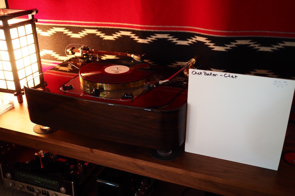
Test pressing from Analogue Productions of Chet Baker's 'Chet'.
What I can tell you, is that between being able to adjust the high-frequency attenuation with the L-pads and the R3 notch filter, my A5 crossovers are really getting dialed in and working extremely well, and it is amazing what these ancient Altec A5 theatre loudspeakers can do!
For example, listening to the Analogue Productions test pressing of Chet Baker's Chet (above) with L-pads turned down between a third and half-way, and the R3 notch filter with about 30-35 Ohms total resistance, sounds astonishingly musical and mesmerizing, which is somewhat contradictory to what the SPICE plots of the 24 Ohm R3 calculations of Pete's suggests. Chalk it up to system / room / personal preference / position of the planets / variables, I guess.
Here's the bottom line: Use calculations to help understand how the variables affect the response curves, and use that to inform your decisions on what to do, but at the end of the day trust your ears.
For me, balancing the adjustment of the L-pads down, and keeping the notch filter R3 up at higher resistance, gives incredibly musical results.
About wire: I've got Duelund DCA16GA as speaker cables going to my Altec's, and it trounced my Western Electric WE16GA in that position, sounding more musically compelling and natural.
The Duelund DCA16GA as speaker cables is really nice.
However, for the wire from the crossovers to the drivers the tables were turned, and the Western Electric WE16GA ended up sounding more musical in that position, being more musically natural and compelling in the way music was presented.
To be fair, the Western Electric has a ton of hours on it, and the Duelund DCA16GA had no hours on it, so I should probably run-in the Duelund on the Cable Cooker for a while before making a final decision.
Ok, that's all for tonight, and I want to thank Pete Riggle for all the work he put into doing the SPICE calculations and working up the figures for the various L-pad and notch filter combinations, it was very illuminating!