
I am delighted to say that the vintage Altec-Lansing A5 Voice of the Theatre Project is now moving forward again!

Jeff's A5 VOTTs as restored by Gary Fischer.
In the first phase of the project I commissioned Gary Fischer to restore a vintage pair of Altec-Lansing A5 Voice of the Theatre loudspeakers, which I described in three parts: Part 1, Part 2, and Part 3.
Many thanks to Gary Fischer for his excellent restoration of the A5 VOTTs!

Jeff's A5 VOTTs without grills.
For my restoration, I chose two 825B bass horn cabinets, two 16 Ohm 515B Alnico low-frequency drivers, two N-500-D 'Dividing Networks' (crossovers), two 1005B 10-cell horns, and two 16 Ohm 288C Alnico high-frequency compression drivers, which is a classic Altec-Lansing A5 Voice of the Theatre combination of components from that period.
Resistors and capacitors, and inductors, oh my!
To adapt Frank L. Baum's famous line by Dorothy in the Wizard of Oz, "Lions and tigers, and bears, oh my!", when you enter the haunted forest of DIY circuit modifications, you too (like me) might in trepidation say, "Resistors and capacitors, and inductors, oh my!" Until you actually meet them, that is, and then like Dorothy when she meets the Cowardly Lion, you might decide that resistors, capacitors, or inductors are really no threat at all, and can actually be quite a nice addition to your audio adventures - that's been my experience.
In the second phase of the project, the plan is to build external crossovers based on the crossover circuit developed by Jean Hiraga using those fearful resistors, capacitors, and inductors, for the combination of the 16 Ohm 515B Alnico low-frequency drivers and the 16 Ohm 288C Alnico high-frequency compression drivers, along with a couple of creative modifications suggested by our good friend Yazaki-san included for good measure.
Important Note: All of what I am describing is for the 16 Ohm version of the drivers, if you have 8 Ohm versions of the drivers you'll need the Hiraga schematic optimized for 8 Ohm drivers, which is not shown here.
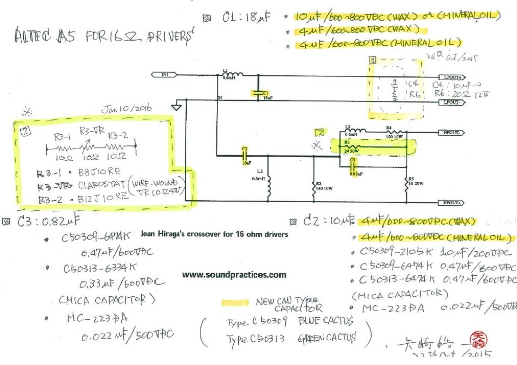
Hiraga-san inspired 16 Ohm A5 crossover with Yazaki-san mods.
You can see Modification 1 and Modification 2 that Yazaki-san drew in the schematic above.
Modification 1: In the first modification Yazaki-san incorporated an impedance compensator into the low-frequency part of the Jean Hiraga inspired circuit, which you can see in the upper right-hand of the diagram above.
If I understand this modification correctly (I'll ask Yazaki-san to clarify just in case), it is similar in concept to the SPEC RSP-901EX Real Sound Processor that I wrote about for Positive Feedback in Issue 78, which reduces fluctuations of loudspeakers' impedance over the frequency spectrum, making them sound more clear, natural, and musical throughout their range.
In this modification a 10uF capacitor (C4 in the diagram above) is placed in series with a 20Ω 12W resistor (R6 in the diagram above) between the +/- low-frequency outputs from the crossover.
Yazaki-san recommended a 20Ω 12W Ohmite Brown Devil resistor for R6 in this application, which I ordered from Digi-Key Electronics (I ordered the B8J20RE-ND 20Ω 8W version as they didn't have a 12W version in stock).
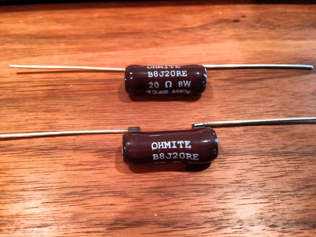
Ohmite Brown Devil 20Ω 8W resistors for Modification 1.
As I brushed the mental cobwebs aside from 6 months ago when we started the planning for this crossover project, I realized I did not have a suitable 10uF capacitor to use in the C4 position, so I'll have to ask Yazaki-san for a recommendation on what to get.
The plan is to first construct the crossovers without Modification 1 in the circuit, so I can hear the crossovers without Mod 1 to establish a baseline, and then I'll add it into the circuit so I can articulate the sonic & musical effects it has on the circuit. Yes, I'm slowly learning not to make too many changes at once, so I can tell what's going on with a circuit!
Modification 2: Unlike the stock Altec N-500-D crossover, Jean Hiraga's A5 crossover design doesn't include a way to adjust the level of the high-frequency horn so you can more easily match it to a room, a feature which I've found to be very handy with the Altec N-500-D crossovers of my 'Stokowski' A7 VOTTs.
I discussed with Yazaki-san how we might approach including adjustability as a design feature in our A5 crossover project, and he proposed a very clever addition to the high-frequency circuit using vintage Clarostat variable resistors, which he was able to find in Japan, and then sent them to me as part of a 'crossover kit' he made up for me. Thank you Yazaki-san, you're the best!
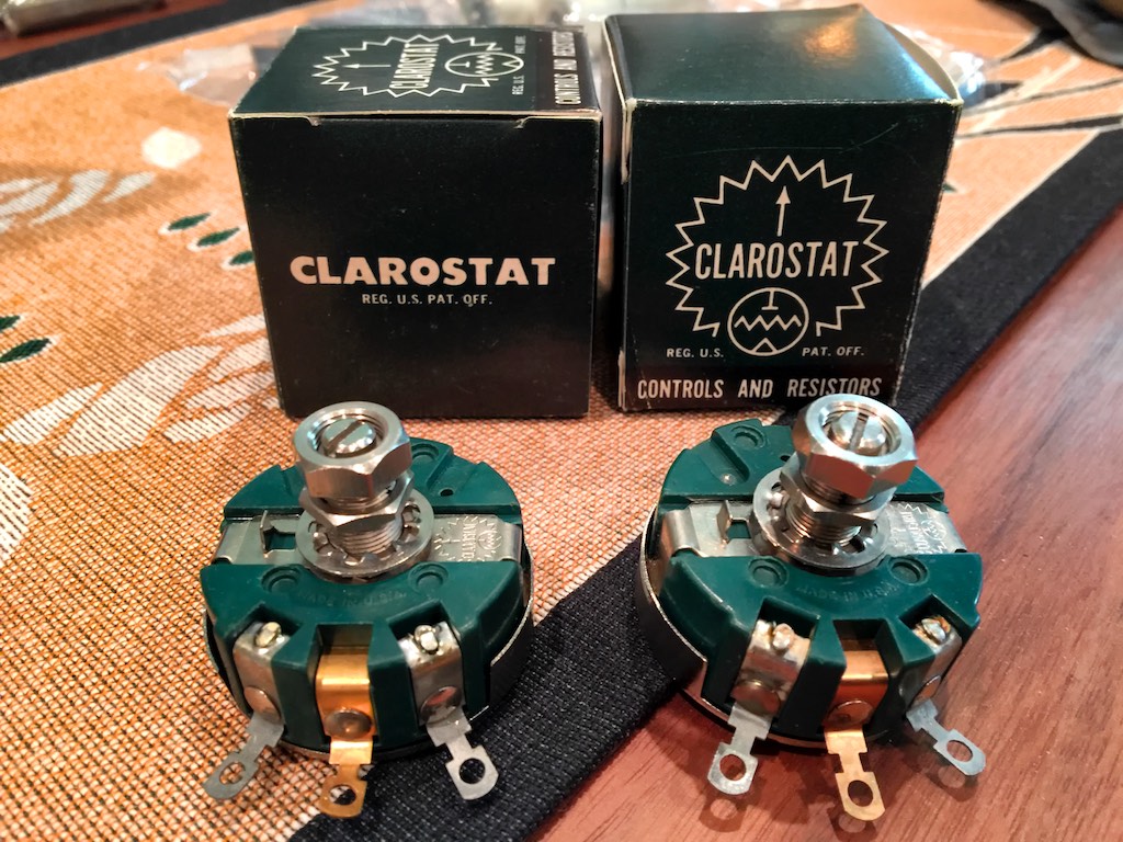
Clarostats for impedance compensation of the high-frequency circuit.
In Modification 2 Yazaki-san replaces the original R3 24-Ohm 50W resistor in the high-frequency circuit with three resistors in series, an R3-1 Ohmite Brown Devil B8J10RE 10Ω 8W resistor, the Clarostat variable resistor, and an Ohmite Brown Devil B12J10RE 10Ω 12W resistor, as depicted at the left middle of the crossover schematic above, with the components shown below.
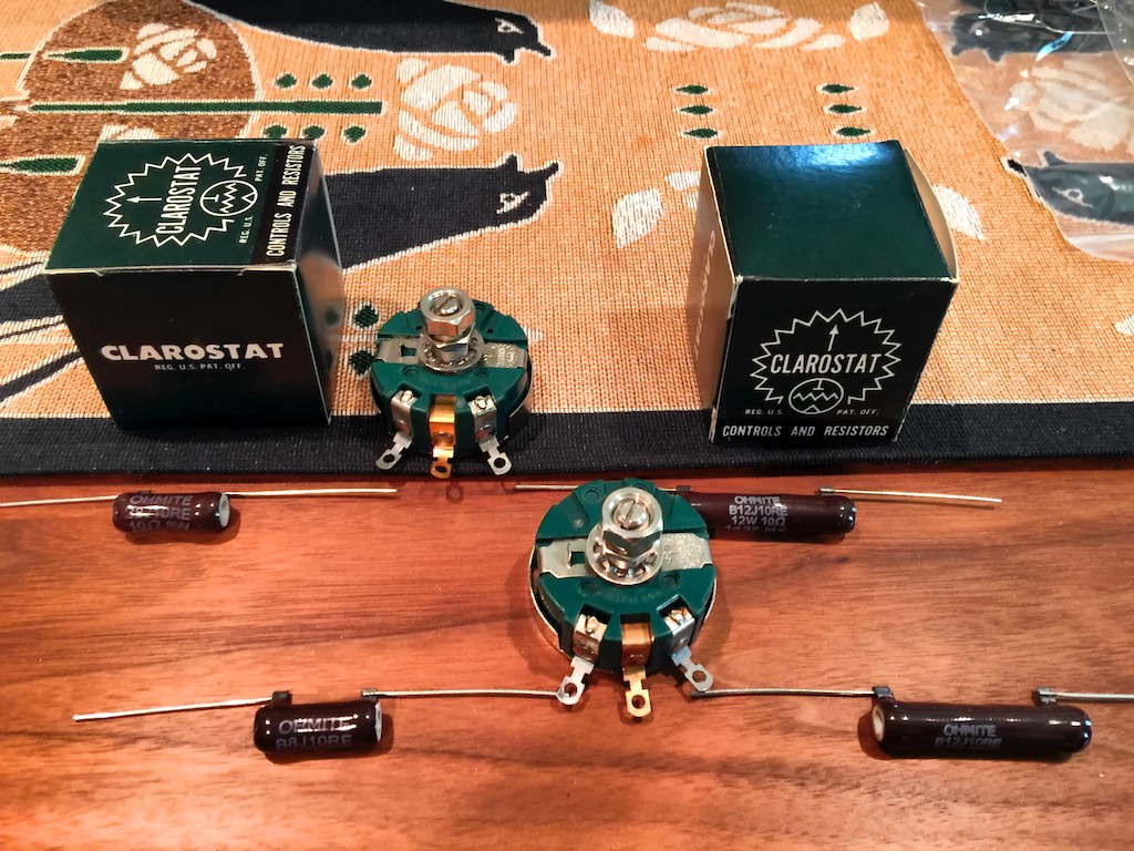
Clarostat variable resistors with Ohmite Brown Devil resistors.
With the arrival of the six custom 6.6uH inductors from Solen Electronique I mentioned in my last post, I thought I now had all the components I needed to start breadboarding the crossovers, but then I realized I was still missing some key capacitors that I still needed to order.
So my first step was to inventory all of the components I had in-hand for the Altec A5 VOTT 16-Ohm crossover project, and then order what I still needed.
The complete list of components for the A5 VOTT crossover project are listed below, and those highlighted in yellow I still need to order. Once I get those ordered I'll update the list so you know what I decided on for a given component.
C1 18uF: Yazaki-san suggested connecting several capacitors in parallel to achieve 18uF. I don't have these, so I've asked Yazaki-san for a recommendation on what to order. I also asked me buddy Pete Riggle for his thoughts on a recommendation, as Pete just built some Hiraga-san inspired 8-Ohm crossovers for his A7 VOTTs that turned out great. Pete graciously offered to loan me the caps needed so I could start breadboarding.
- 10uF/600-800VDC wax or mineral oil capacitor
- 4uF/600-800VDC wax capacitor
- 4uF/600-800VDC mineral oil capacitor
C2 10uF: Yazaki-san suggested connecting capacitors in parallel to achieve 10uF as he did for C1.
- 4uF/600-800VDC wax capacitor
- 4uF/600-800VDC mineral oil capacitor
- SPEC CORP 1uF/200VDC C50309-2105K (included in Yazaki-san's crossover kit).
- AZ Cap Blue Cactus 0.47uF/600VDC C50309-6474K (included in Yazaki-san's crossover kit).
- AZ Cap Green Cactus 0.47uF/600VDC C50313-6474K (included in Yazaki-san's crossover kit).
- SPEC CORP Ruby-Mica 0.022uF/500VDC MC-223DA (included in Yazaki-san's crossover kit).
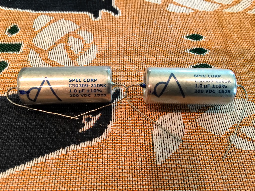
SPEC CORP 1uF/200VDC C50309-2105K capacitors for C2.

AZ Cap Blue Cactus 0.47uF/600VDC C50309-6474K for C2.

AZ Cap Green Cactus 0.47uF/600VDC C50313-6474K capacitors for C2.
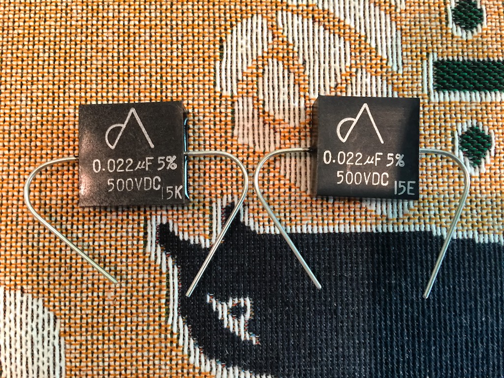
SPEC CORP Ruby-Mica 0.022uF/500VDC MC-223DA capacitors for C2.
C3 0.82uF: Like C1 and C2 several capacitors are paralleled to achieve 0.82uF.
- AZ Cap Blue Cactus 0.47uF/600VDC C50309-6474K (included in Yazaki-san's crossover kit).
- AZ Cap Green Cactus 0.33uF/600VDC C50313-6334K (included in Yazaki-san's crossover kit).
- SPEC CORP Ruby-Mica 0.022uF/500VDC MC-223DA (included in Yazaki-san's crossover kit).
AZ Cap Blue Cactus 0.47uF/600VDC C50309-6474K for C3.

AZ Cap Green Cactus 0.33uF/600VDC C50313-6334K for C3.
SPEC CORP Ruby-Mica 0.022uF/500VDC MC-223DA capacitors for C3.
C4 10uF: This is the capacitor part of Yazaki-san's Modification 1 that I described above. In Mod 1 a 10uF capacitor is placed in series with a 20Ω 12W resistor (R6) between the +/- low-frequency outputs from the crossover to reduce fluctuations of loudspeakers' impedance over the frequency spectrum.
- 10uF capacitor
R2 140 10W: In case you're wondering where R1 is, there is no R1 in the Hiraga-san crossover schematic. To get R2 140 10W Yazaki-san recommended a series resistor connection of 100 Ohms & 40 Ohms Ohmite Brown Devils. Digi-Key didn't have the 10W versions in stock so I substituted 12W versions.
- Ohmite Brown Devil B12J100E-ND 100 Ohms 12W
- Ohmite Brown Devil B12J40RE-ND 40 Ohms 12W
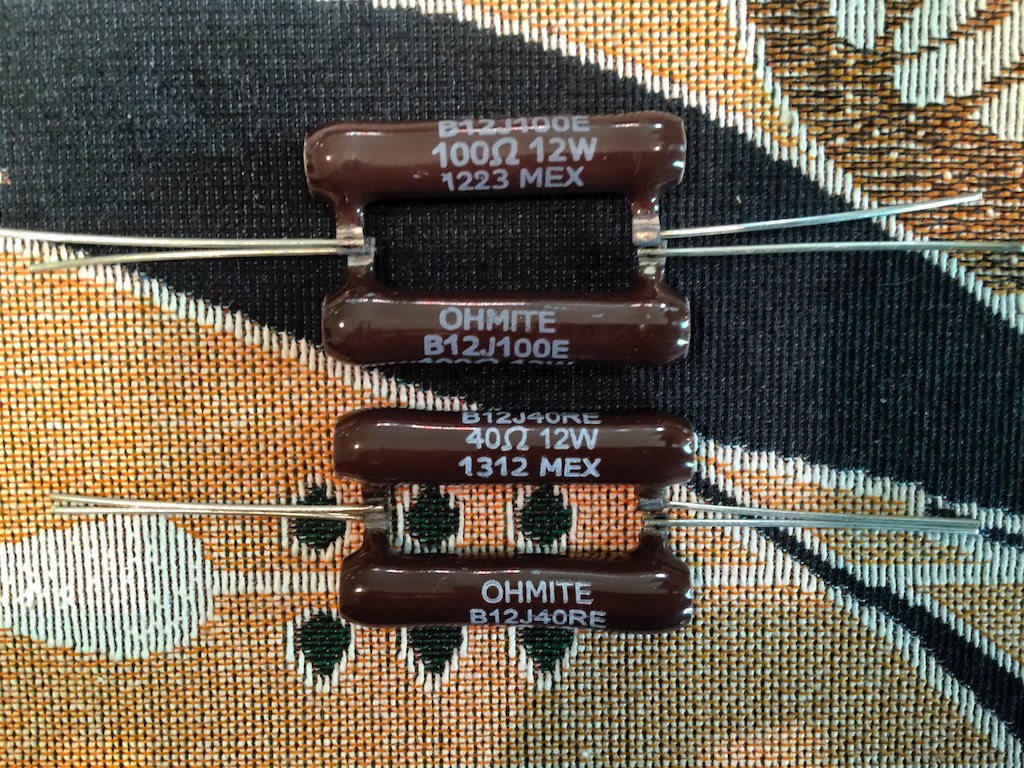
R2 140 10W achieved with Ohmite Brown Devil B12J100E-ND 100 Ohms 12W in series with Ohmite Brown Devil B12J40RE-ND 40 Ohms 12W.
R3 24 50W: In Modification 2 Yazaki-san replaces the original R3 24-Ohm 50W resistor in the high-frequency circuit with three resistors in series, an R3-1 Ohmite Brown Devil B8J10RE 10Ω 8W resistor, the Clarostat variable resistor, and an Ohmite Brown Devil B12J10RE 10Ω 12W resistor, as depicted at the left middle of the crossover schematic above, with the components shown below.
- R3-1 Ohmite Brown Devil B8J10RE 10Ω 8W resistor (included in Yazaki-san's crossover kit).
- R3-2 Clarostat variable resistor (included in Yazaki-san's crossover kit).
- R3.3 Ohmite Brown Devil B12J10RE 10Ω 12W resistor (included in Yazaki-san's crossover kit).
Clarostat variable resistors with Ohmite Brown Devil resistors as used in Mod 2 for R3.
R4 100 10W: Ohmite Brown Devil B12J100E-ND 100 Ohms 12W.
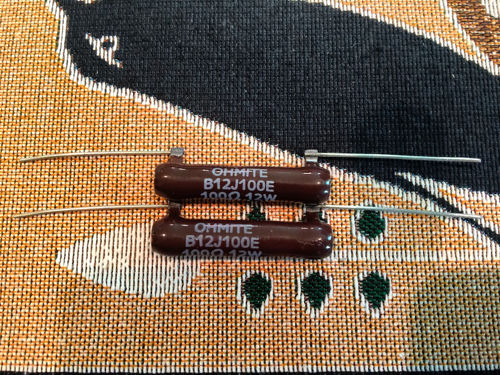
Ohmite Brown Devil B12J100E-ND 100 Ohms 12W resistors for R4.
R5 10 20W: Ohmite Brown Devil B12J10RE-ND 10 Ohms 12W

Ohmite Brown Devil B12J10RE-ND 10 Ohms 12W for R5.
R6 20 12W: This is the Ohmite Brown Devil resistor part of the low-frequency impedance compensator addition by Yazaki-san that is described above in Modification 1, where a 10uF capacitor (C4) is placed in series with a 20Ω 12W resistor (R6) between the +/- low-frequency outputs from the crossover to reduce fluctuations of loudspeakers' impedance over the frequency spectrum..
Ohmite Brown Devil 20Ω 8W resistors for Modification 1.
L1, L2, and L3 6.6mH inductors: It took Solen Electronique only 4 days to make up the six custom 6.6mH inductors for the project and send them to me. 6.6mH inductors are a non-standard value, so I ordered the S166.8 6.8mH versions and Solen custom wound them to 6.6mH for me at no extra charge. What great customer service!
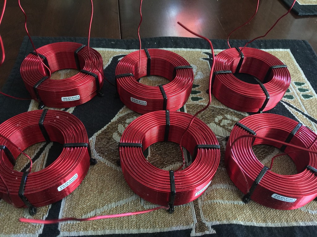
Solen custom 6.6mH inductors for the A5 VOTT project crossovers.
Ok that's the end of the list for capacitors, resistors, and inductors.
McMaster-Carr setscrew lugs: I want to use copper McMaster-Carr setscrew lugs for direct wire-on-wire connections wherever possible, so there’s zero performance loss, like I did with the Duelund-WRSE project. The setscrew lugs are great to work with, and allow easy component swapping for comparisons. I think wire-on-wire connections are probably better sounding than having the additional materials of intervening connectors that the signal has to go through. Pete Riggle recommended I use straight-tongue copper setscrew lugs, 14-8 AWG, #10 stud, from McMaster-Carr, part number 6923K61. I'll place an order when I know how many I'll need.
Wire: I'll use Western Electric WE16GA wire in the crossover where wiring is required.
Ok, now that I've gone through my inventory of parts for the A5 VOTT crossover project I know what's still on my shopping list:
For C1 18uF:
- 2 x 10uF/600-800VDC wax or mineral oil capacitor
- 2 x 4uF/600-800VDC wax capacitor
- 2 x 4uF/600-800VDC mineral oil capacitor
For C2 10uF:
- 2 x 4uF/600-800VDC wax capacitor
- 2 x 4uF/600-800VDC mineral oil capacitor
For C4 10uF: This is the capacitor part of Yazaki-san's Modification 1.
- 2 x 10uF capacitor
I've asked Yazaki-san, Pete-san, and Ron-san for ideas for the capacitor shopping list above, so soon as I hear back I'll go capacitor shopping, then all I'll need is the McMaster-Carr setscrew lugs.
Many thanks to Yazaki-san for all his great ideas for the A5 VOTT crossover project, and his generosity in sending me a 'crossover kit' to help kick-off the project! Thank you, Yazaki-san!
A big thanks to Pete who offered to loan me the needed caps on the list above to get me started on breadboarding.
Much more to come, and thanks for stopping by!