

Stephaen sent an early morning email: "I'm going to stop at the El Fat Cat Grill taco truck and get us lunch, and I'll meet you and Pete at your place at noon."
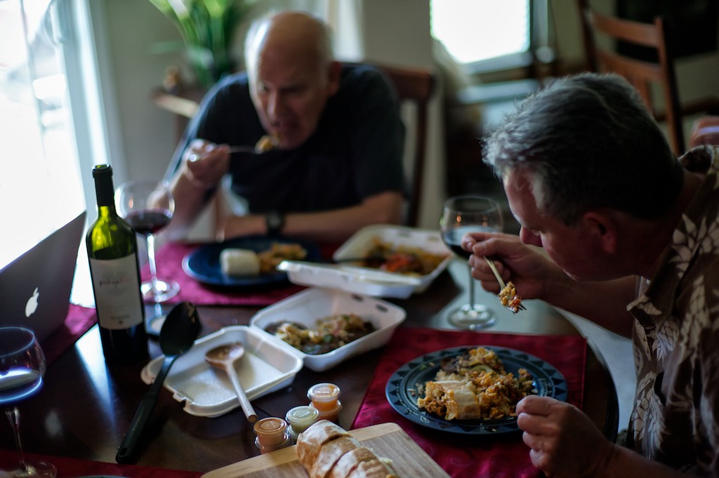
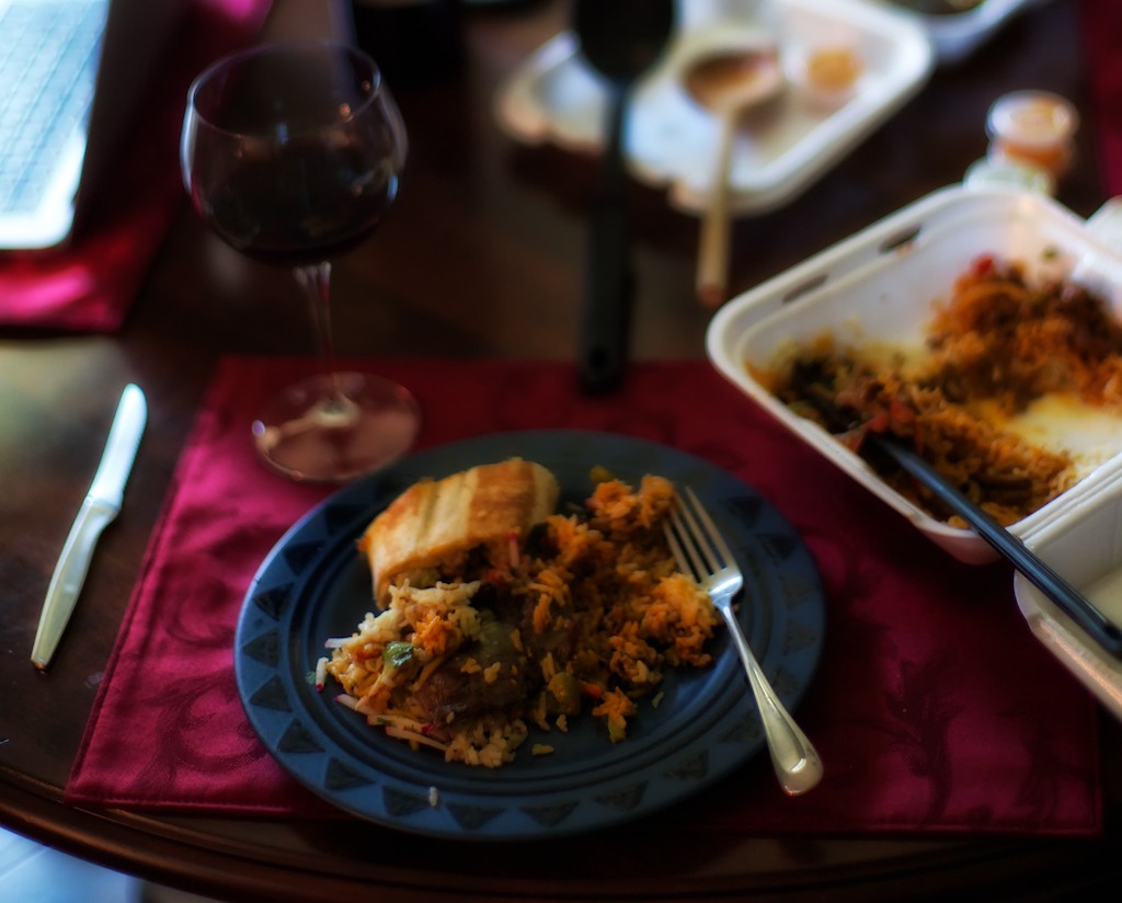
While the El Fat Cat Grill is actually a taco truck, referring to it as 'taco truck' is like referring to the Sistine Chapel as "a room about the size of a basketball court". It just doesn't capture the magnificence of the food they do. I think Michelangelo would love it!
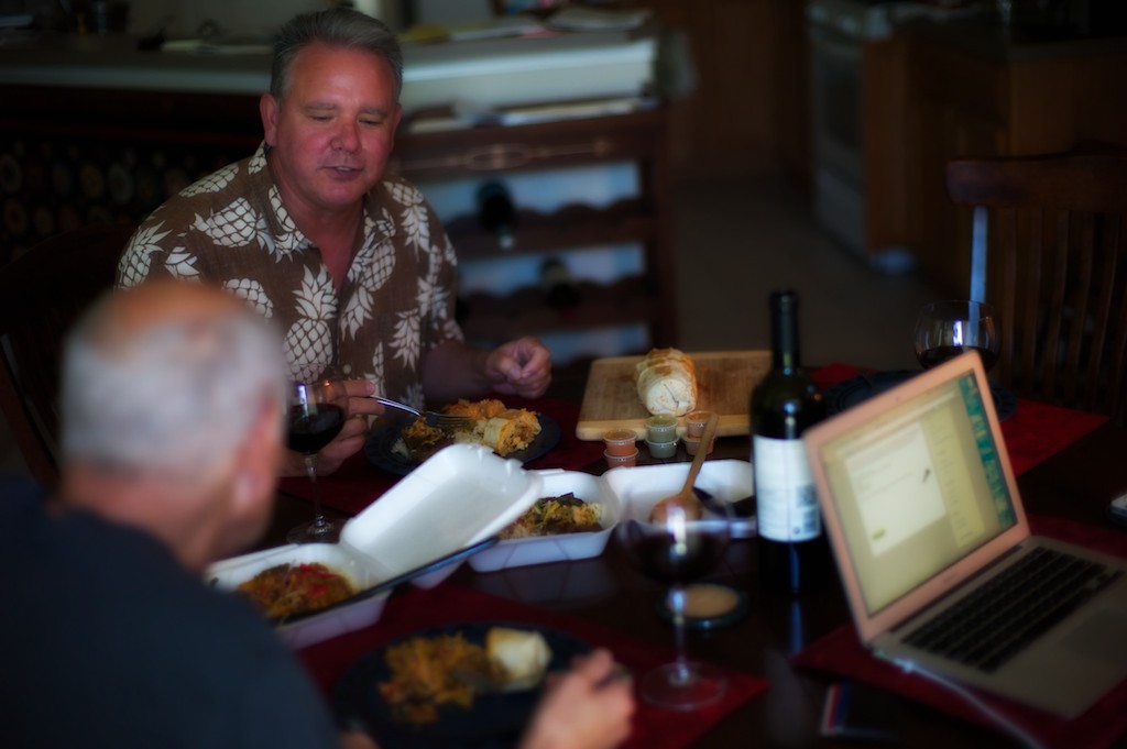
I'll tell you what, it sure is a pleasure to have Stephaen Harrell (6Moons) and Pete Riggle (Pete Riggle Audio Engineering) helping guide the Duelund-WRSE Project along. Not only are Stephaen & Pete good friends, with the laughs, good food, good wine, good music, and general merry making that you would expect to be involved in such a gathering, but they both have oodles of experience building big horn loudspeakers and crossovers from scratch. That's priceless - thanks guys!
Caution: If you choose to try and duplicate what I am doing with my WRSE to modify your own loudspeakers, you do so at your own risk, and you are solely responsible for any damage or harm you inflict upon yourself, your loudspeakers, or your domestic relationship. If you burn your house down inadvertently while doing this, that one's on you too. 😉
The plan for the day was to finish breadboarding the Duelund crossover for the Westminster Royal SE and then give it a listen. After we got everything breadboarded, up and running to make sure everything was working correctly, then we'd go back and build an artful chassis for the crossover, add in premium hookup wire, and install the internal Westminster Royal SE Panatela component wire harness that Mark Coles is developing for the project (thanks Mark!). After everything is all in its final configuration, then I'm planning on going back and conditioning the components one-by-one with my Audiodharma Cable Cooker so I can extract the ultimate performance from the new crossovers (if you've ever used one of these devices to condition your cables & power cords you know it makes a BIG performance difference).
Rule number 1: It always takes longer than you think it will, and not just because of the food, wine, and tomfoolery involved either (OK, well maybe a little).
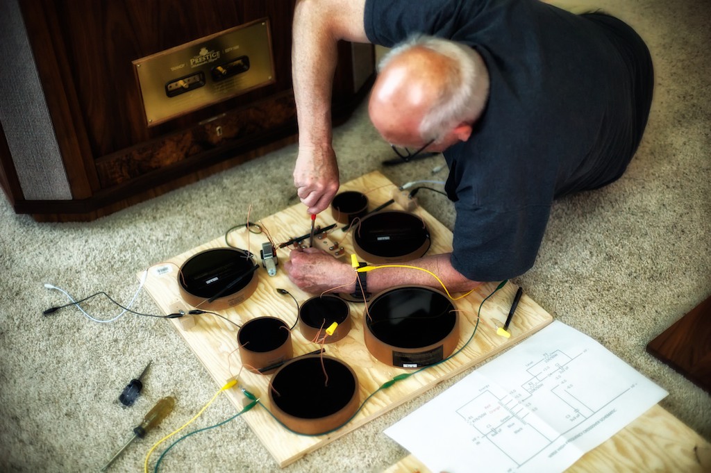
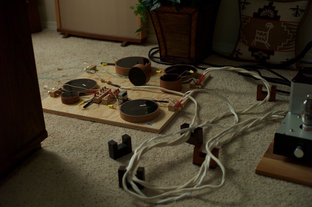
It took us a while to get everything laid out, hardware installed, wired up (with frequent careful reference back to the schematics), before we had a complete breadboarded Duelund crossover for the left Westminster Royal SE.
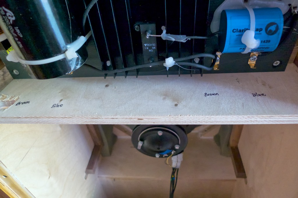
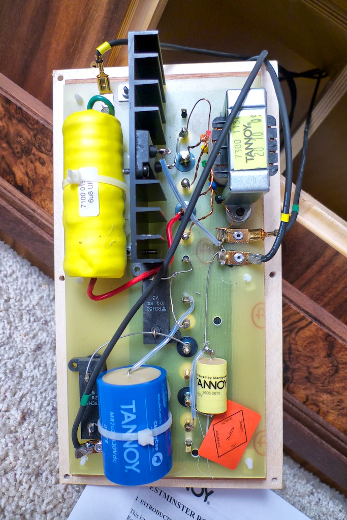
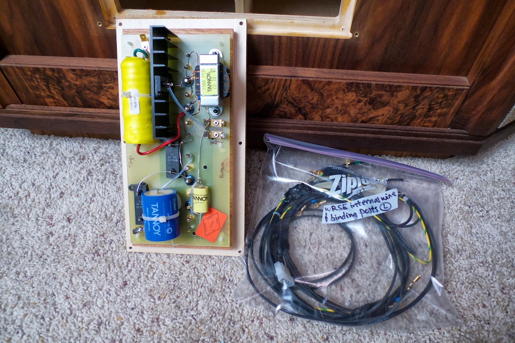
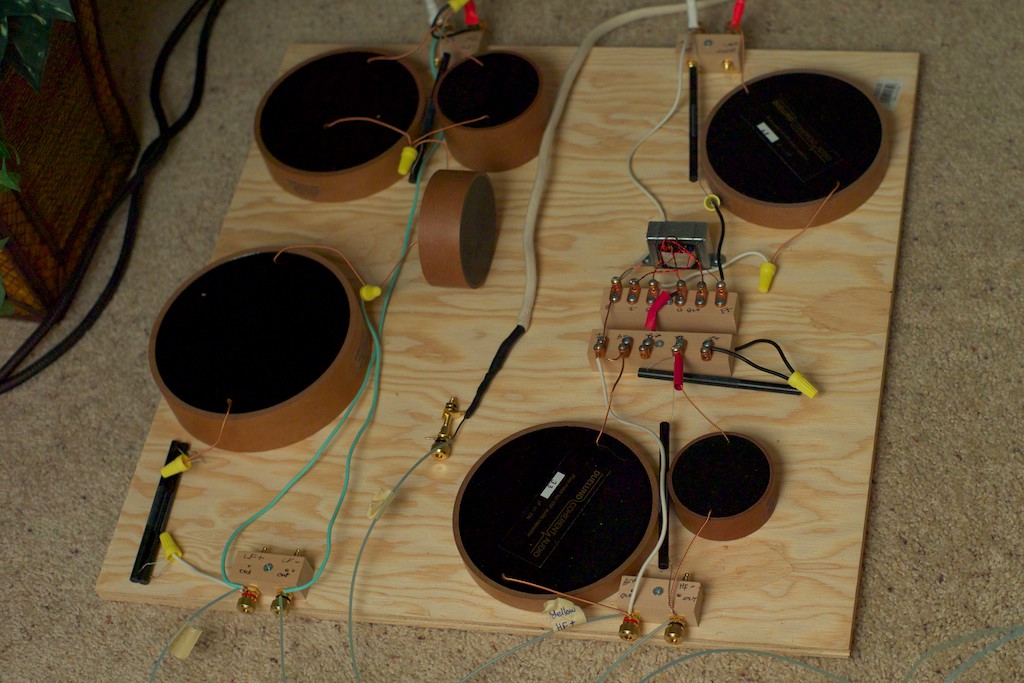
If you look in the photo below there are two complete crossover boards on the breadboard: on the left is the low frequency crossover, and on the right is the high frequency crossover.
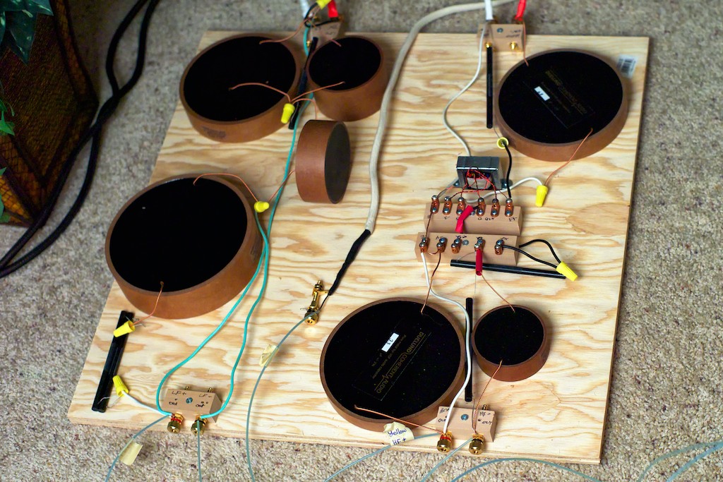
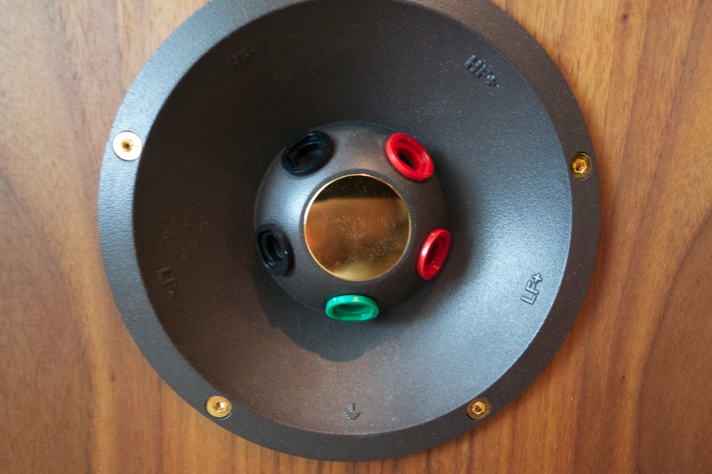
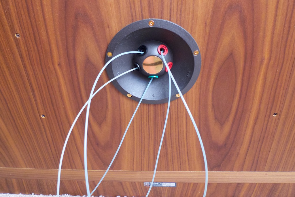
I decided I wanted to maintain the adjustability (treble energy & treble roll-off) of the high frequency section of the crossover that is normally located on the front panel of the WRSE (photo below), so we relocated it to the outboard crossover and used copper set screw lugs for direct wire-on-wire connections so there's zero performance loss as there is with the stock adjustors. You have to move a wire around to change the settings, but maintaining the purity of the signal more than makes up for the hassle of having to loosen a screw and move a wire.
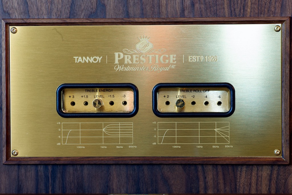
Here's a closeup of the treble energy & treble roll-off adjustors for the high frequency section of the crossover. Not pretty yet, we'll be thinking about that, but extremely effective in maintaining sonic purity while allowing adjustability.

I've got to run off and do a little grocery shopping, but when I get back I'll tell you the rest of the story!
Ok, I'm back, and the refrigerator and wine rack have been restocked.
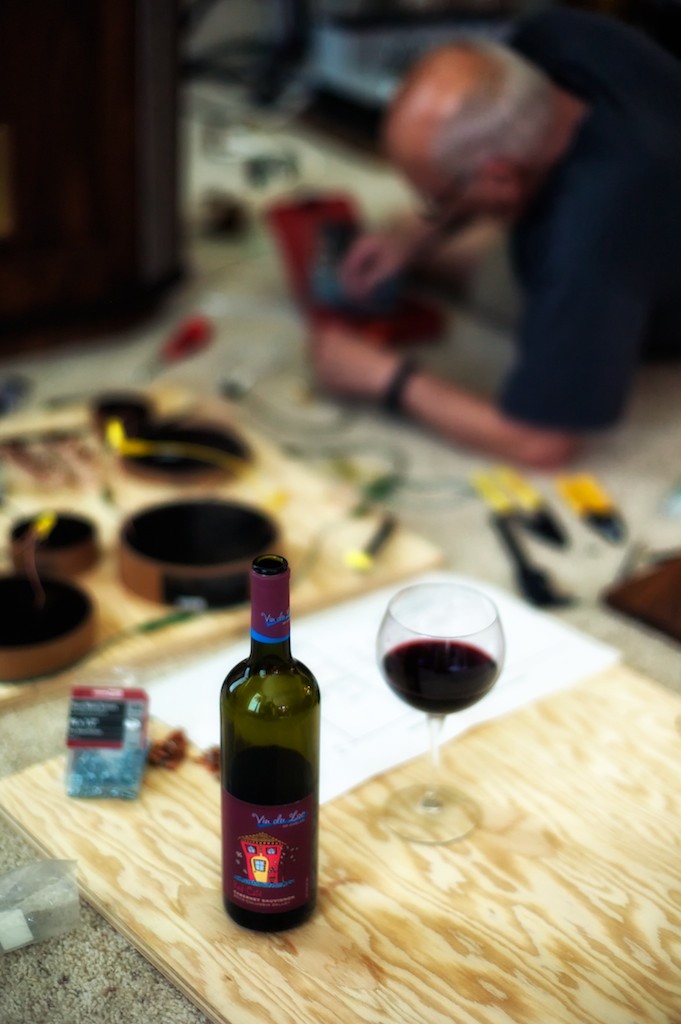
Let's continue the story: Pete and Stephaen had to wander off for other commitments, leaving yours truly to finish up installing the outboard Duelund crossover we put together for the left WRSE.
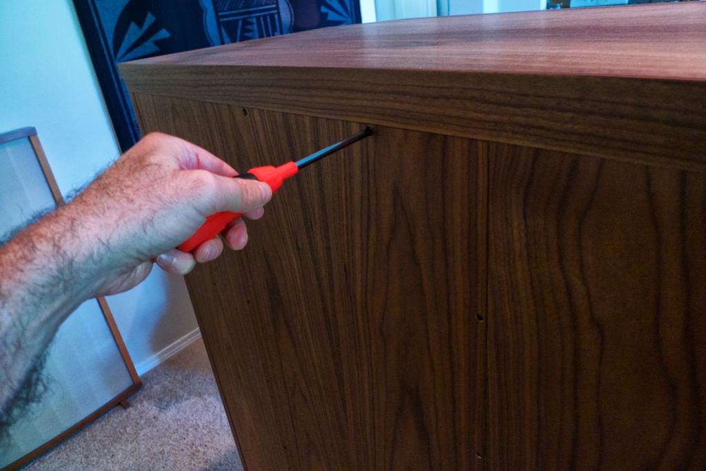
The next step was opening up the big Westminster by removing the back panel screws with a # 2 Philips screwdriver. After taking out the screws and setting them aside I lifted out the back panel and set it down.
Caution: My back panel came out easy, but Tannoy says the back panel is often a tight fit and warns that owners should not try to pry it out or you could damage the cabinet. Rather, Tannoy says to instead go around the outside of the panel while "thumping it firmly with your fist" until it starts to loosen up and move, then you can lift it out.
I then removed the WRSE's internal wires from speaker binding posts mounted in back panel.
Closer:
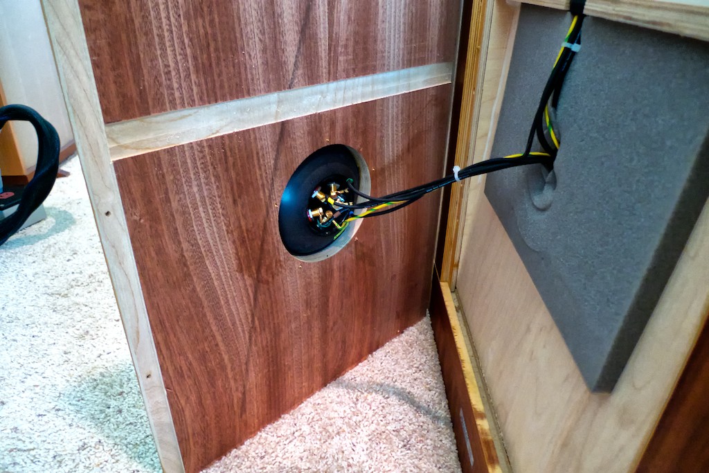
Closer still:
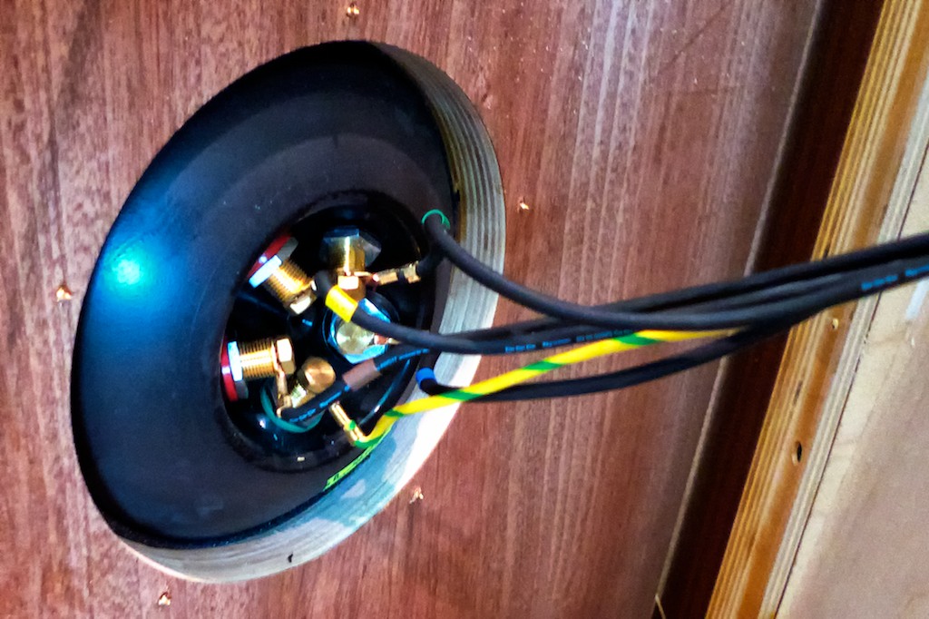
The wires are held to the binding posts with an 8mm bolt, so I first loosened the bolt with an 8mm wrench, then removed the 8mm bolts with a socket to speed the job.
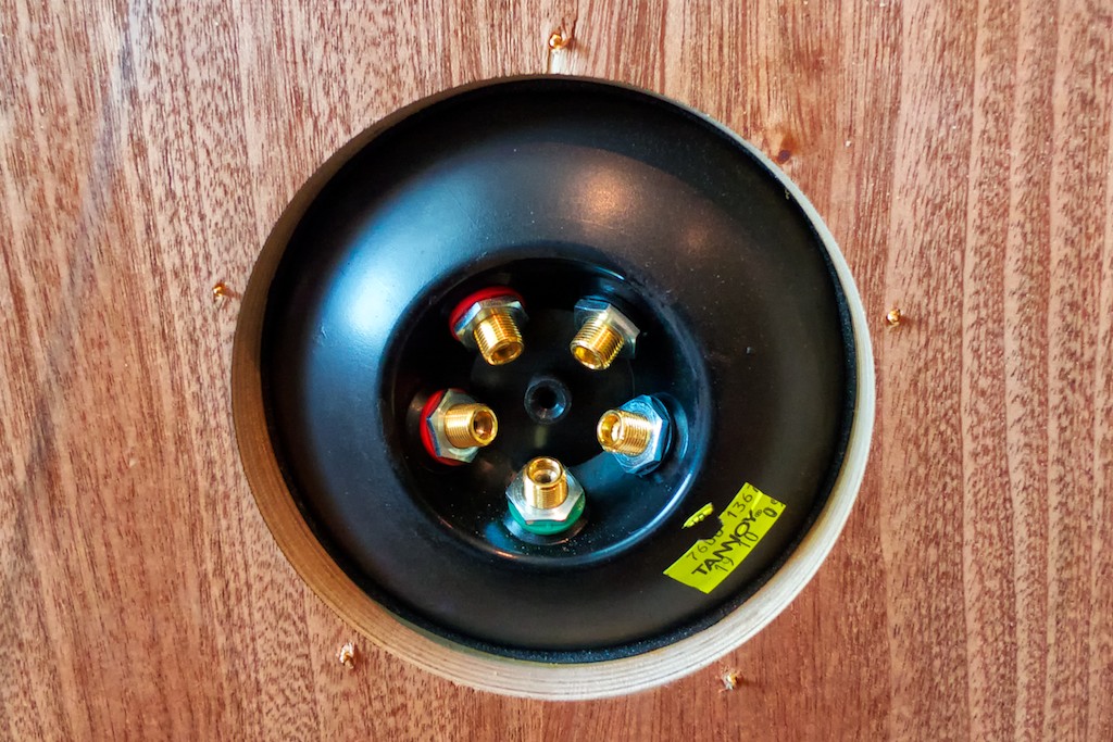
Once done with that I removed the nuts holding the binding posts in place, I then removed the binding posts from the terminal panel, and then set the back panel aside. When the binding posts have been removed from the terminal panel the holes are just the right size to thread the new cable harness through when the time comes.
Before you start unplugging the wiring harness label everything just in case!
LF crossover labeled according to color codes.
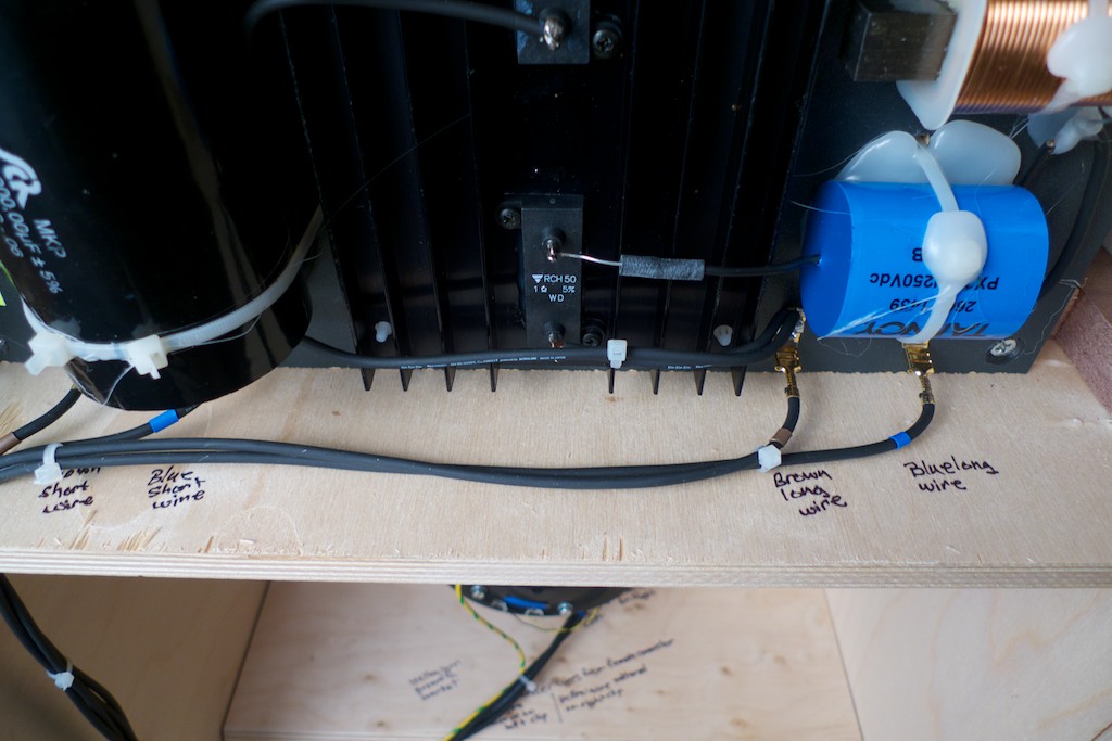
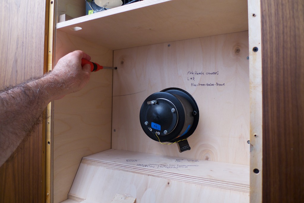
Next I labeled the harness color codes on the inside of the cabinet, as well as the position of the tweeter wires and grounds.
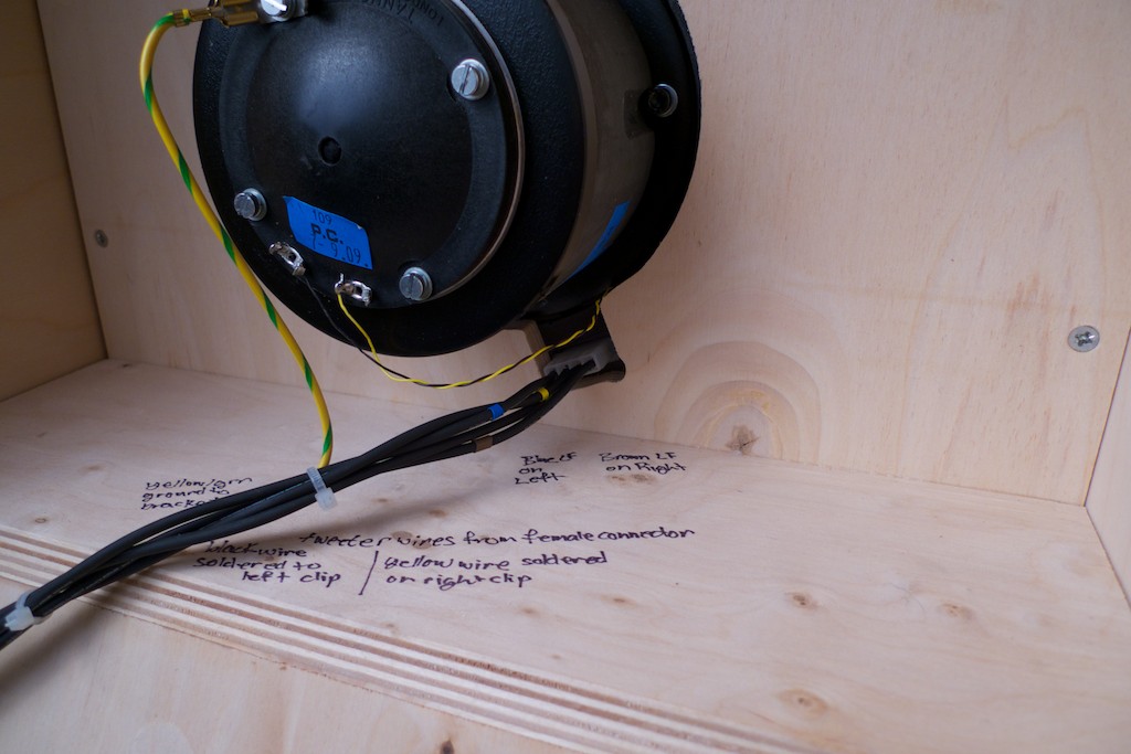
Another view:
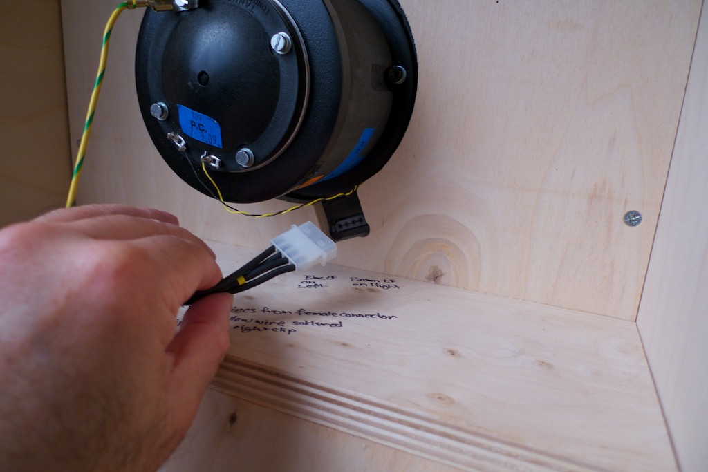
Next I unplugged the drive unit wiring harness male connector from the female connector. It just pulls straight out.
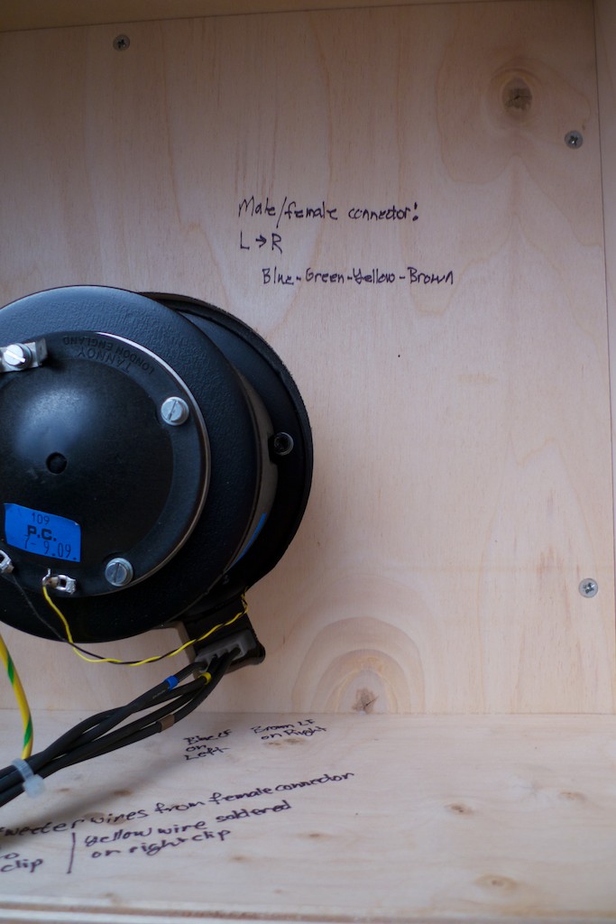
The color coding scheme Tannoy uses for the internal wiring harness follows this convention:
Brown LF +ve
Blue LF –ve
Yellow HF +ve
Green HF –ve (this wire is black on from female connector to the driver)
Green/ yellow Earth
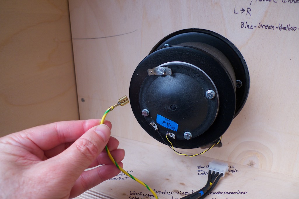
Unplug the yellow/green ground wire.
Now unplug the four wires from the low frequency crossover.
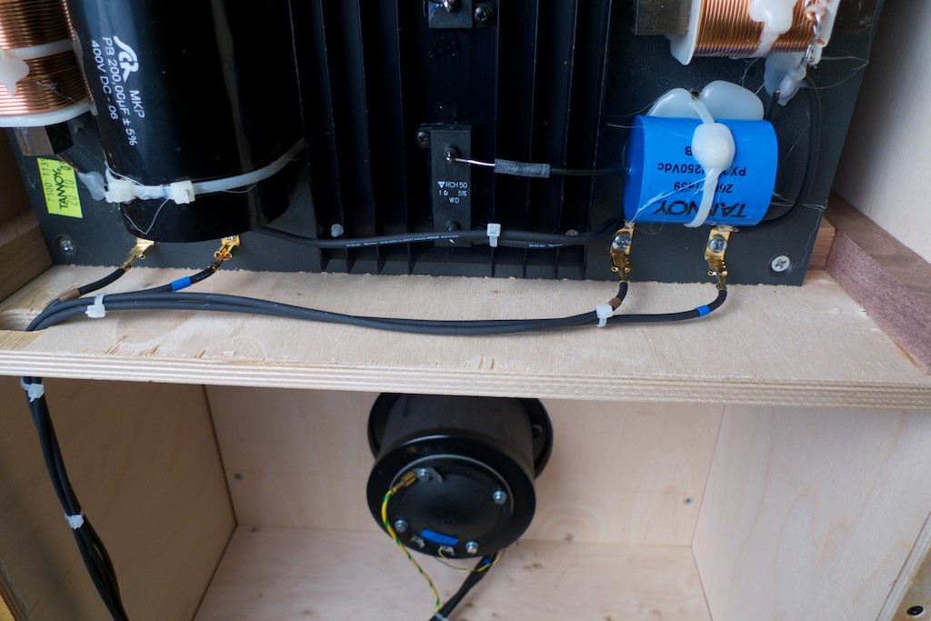
Next I pulled the wires down through their routing holes to get them out of the way for the next steps.
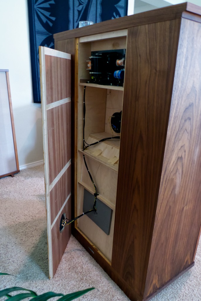
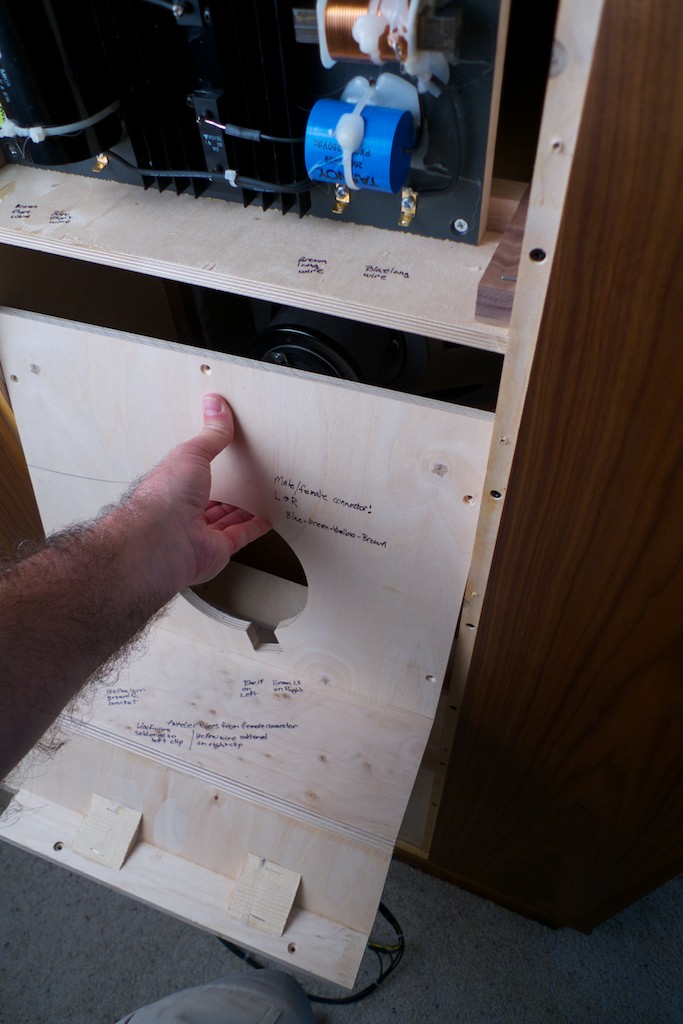
I pulled the wires down through the second routing hole too and let the wire harness rest on the floor. Next I removed the screws that hold the internal plywood structure that seals the bass horn in place with a # 2 Phillips screwdriver. There's two screws as seen in the photo below and ...
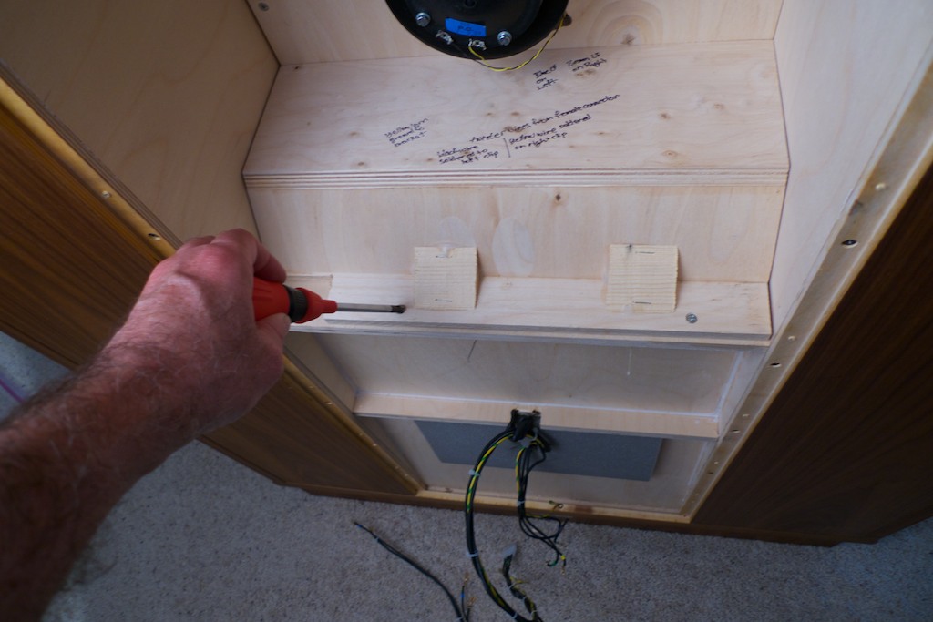
... then I removed the 5 screws from around the driver of the internal plywood structure that seals the bass horn.
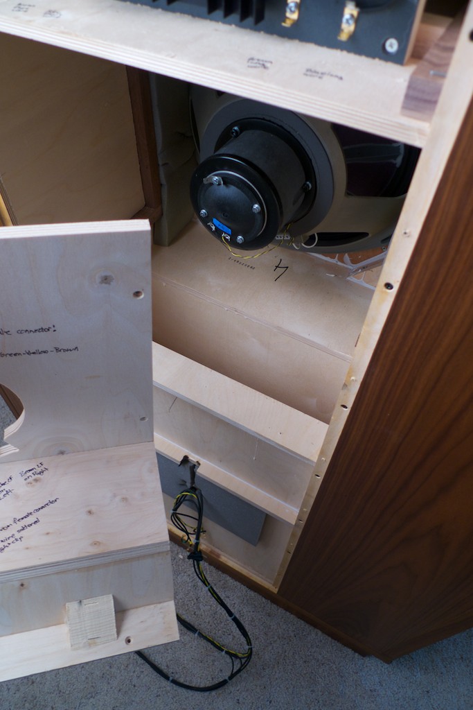
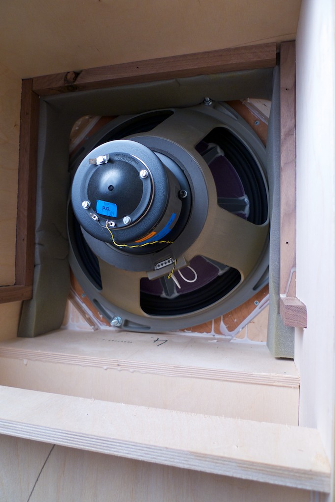
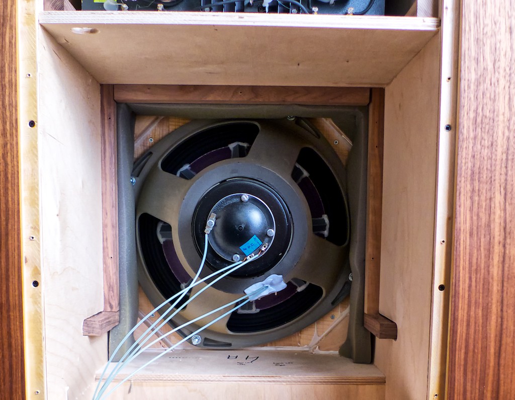
Next I lifted out the internal structure to expose the driver, then set the inner structure aside.
I am going to connect the new internal Panatela wiring harness that Mark Coles is making direct to the drivers and direct to the outputs of the crossover, so I will not be using the stock Tannoy male/female plug connector (its said to degrade the sound quality quite a bit). That way I have only the Panatela wire harness in the signal path between the crossovers' outputs and the driver connections, with no connectors.
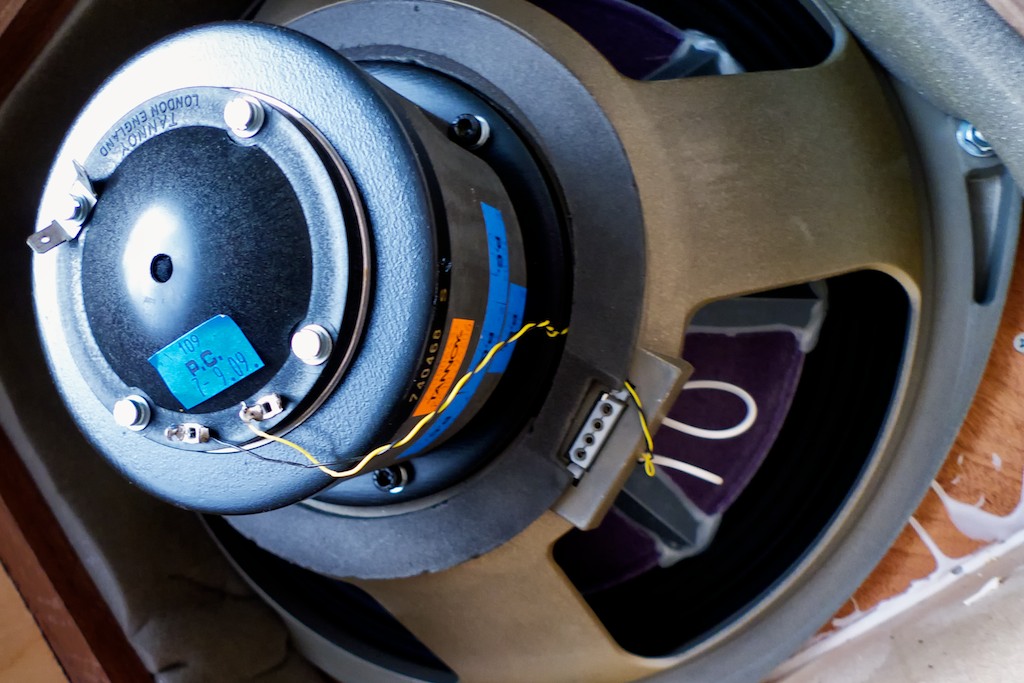
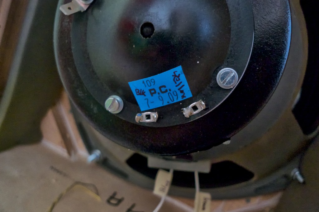
There's two extremely fine wires that go from the female plug connector to the tweeter. There's a little blue tag and I suggest if you're doing a direct connection of cables to the driver like I am, that you label it with the wire connection's color codes. Mine had a yellow wire connected on the right, and a black wire connected on the left. The wires are soldered in place, so I snipped them off to get them out of the way.
Caution: If you choose to desolder / solder the connections for the high frequency wires you need to be extremely quick about it. The two tabs that the yellow & black high frequency wires are attached / soldered to are mounted on a driver endcap that is made of plastic (the one in the photo with the 4 screws holding it in place). If you heat the tabs too long with a soldering iron you'll melt the plastic. This could wreck your day as the endcap has micro-electrical connections deposited in it in high-tech fashion, and it is part of the tweeter assembly. If you melt it you will likely destroy it. That means you'll have to order new ones. They're probably expensive. Be careful!
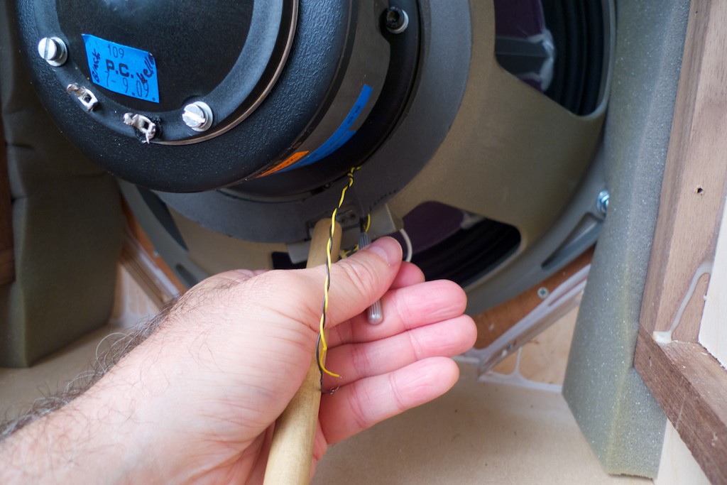
Then I removed the female plug connector from drivers frame. The connector has two little plastic prongs that you have to push in to get clearance so you can push it out (I used a small screwdriver).
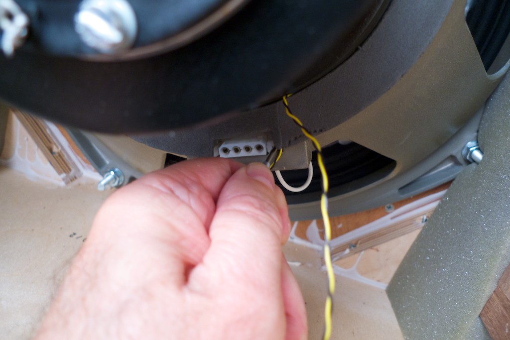
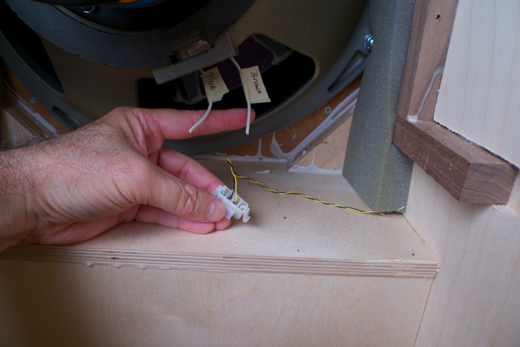
Then I pulled the fine tweeter wires through to free them from opening. I then pushed the female connector out using the handle end of a wooden spoon (use something non-magnetic or it'll be drawn into the powerful magnet of the driver, which is a no-no). Note the color coding and label the wires. Mine had blue (LF -) as the left wire and brown (LF +) as the right wire.
Now it was time to go to work on the high frequency crossover located in the front of the Westminster's cabinet. On the front of the cabinet I removed the 2 brass adjustment screws and set them aside.
I then removed the four 2.5mm hex screws holding the brass trim place in place, pulled out the plastic cups, and then removed the trim plate and set it aside.
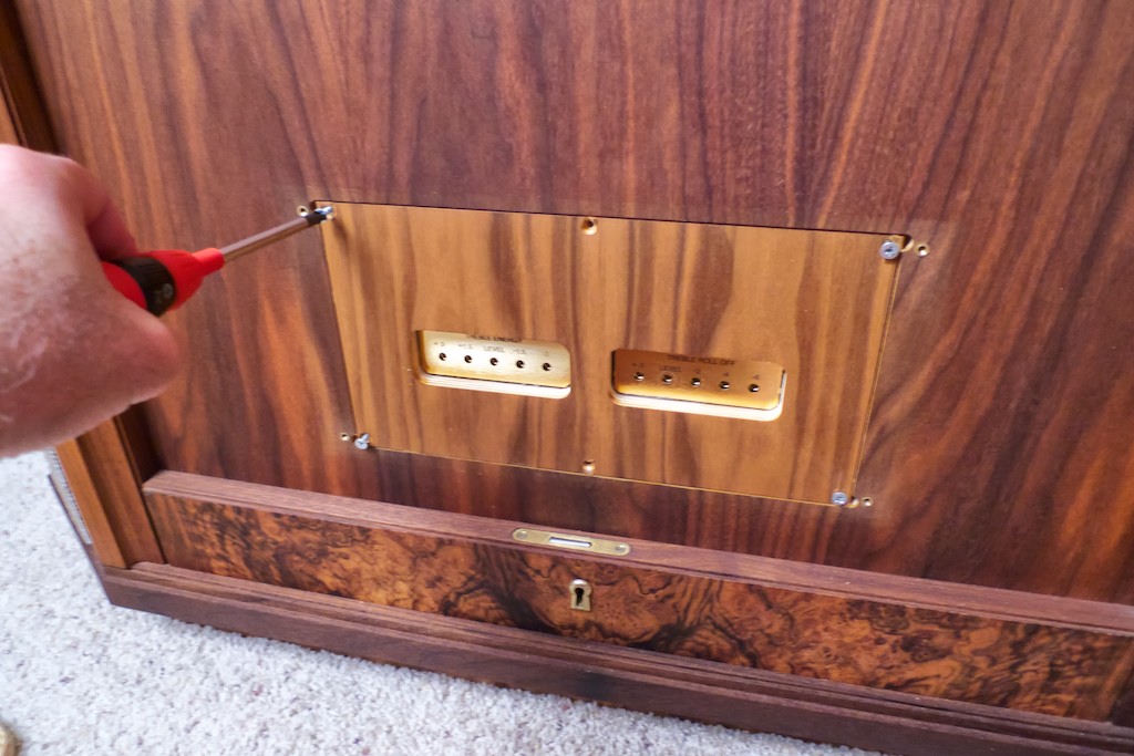
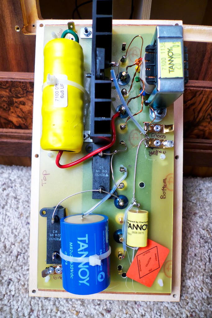
I then removed the 6 wood screws holding the wooden panel and withdrew it to reveal the HF crossover assembly.
I marked the yellow (soldered) and green (press fit) positions on the circuit board by the autoformer with a permanent marker in case I wanted to re-install the stock cable set, so I could remember what went where. I taped the green and yellow wires together and labeled them “bottom by the autoformer”.
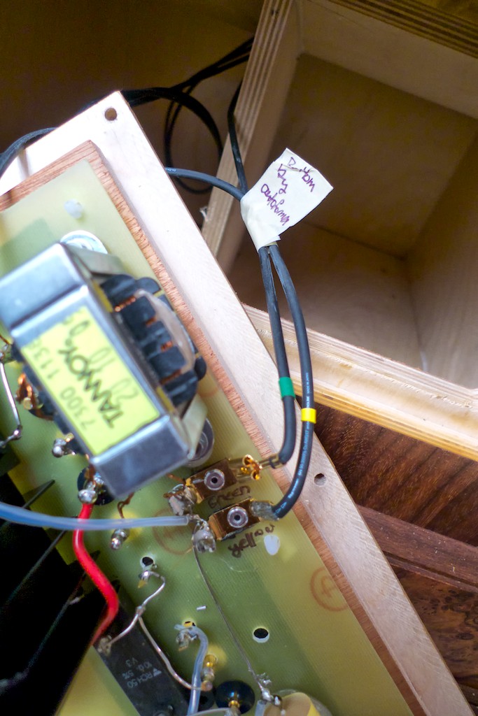
I unplugged the green wire from the circuit board, and then I de-soldered the yellow wire. I then labeled the green (soldered) and yellow (press fit) positions on the top of the circuit board with a permanent marker, and then de-soldered the green wire and unplugged the yellow wire. I taped the two wires together and labeled them “top of the circuit board”.
I then pulled the internal wiring harness out through the back of the speaker and placed it in a plastic bag labeled “WRSE internal wire & binding posts Left” and set it aside in case I need it later.
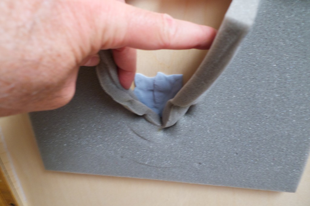
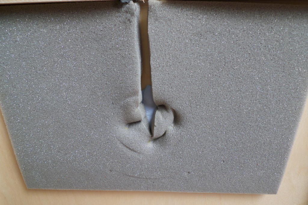
I reinstalled the now disconnected HF crossover back into the cabinet, put back on the trim plate, inserted the plastic cups, and put the selector pins back in place. I then went around back and sealed the wiring harness hole in the back of the horn with Blu-Tack.
Another photo.
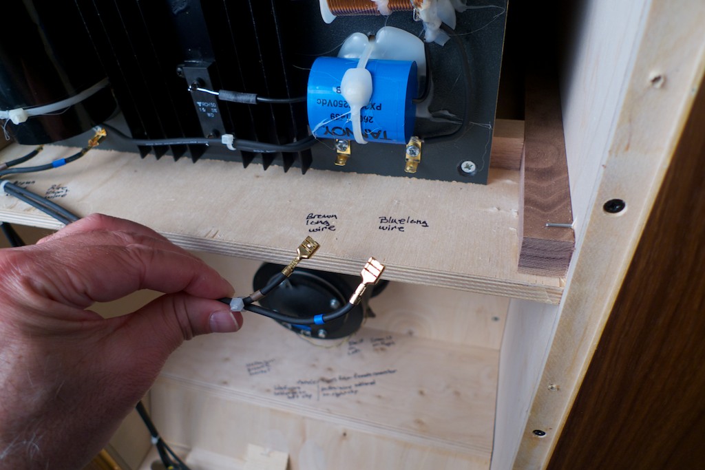
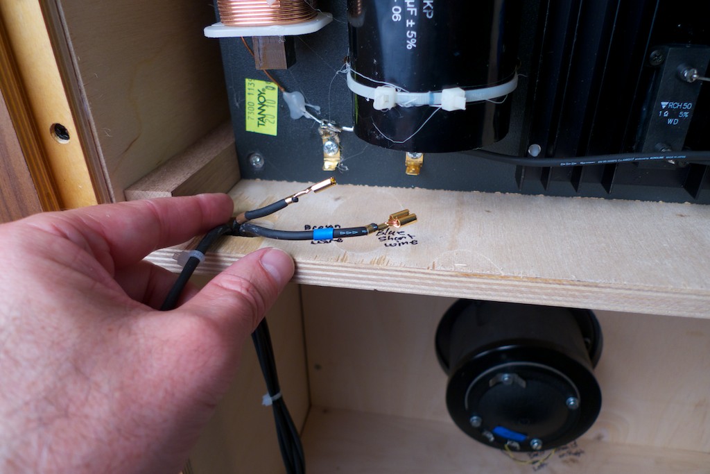
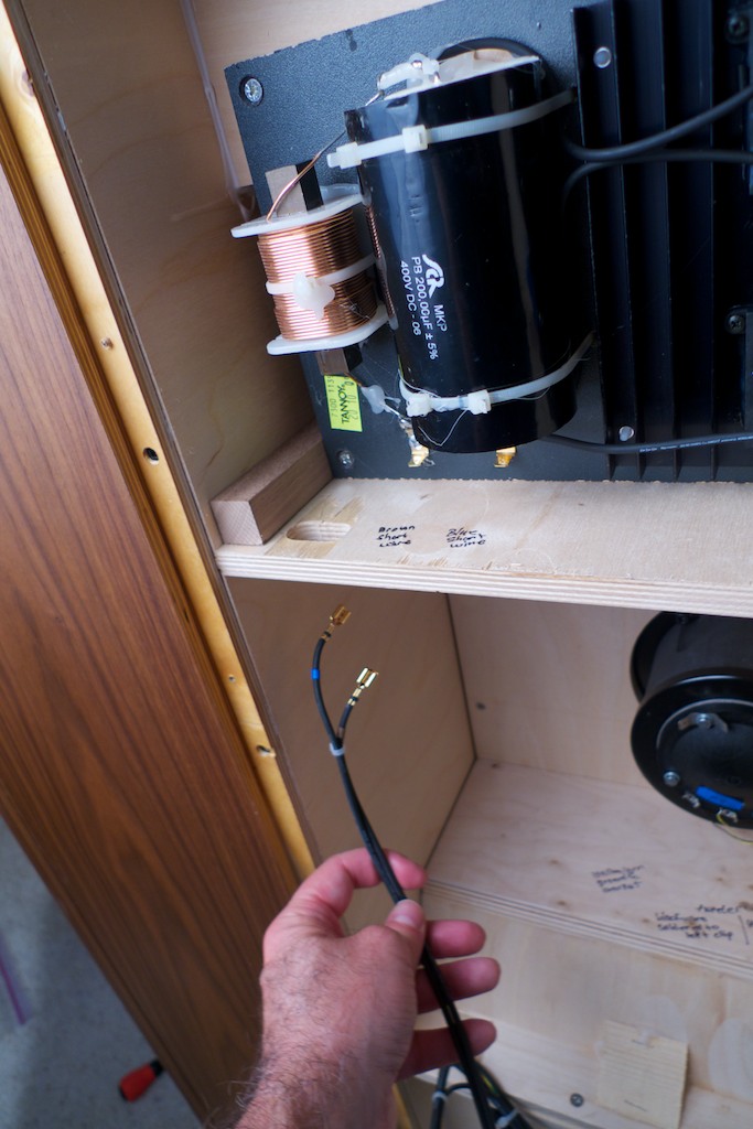
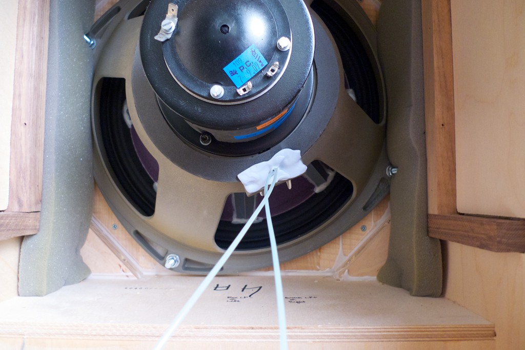
With that done I cut five 77-inch lengths of 47 Labs speaker wire to prototype the direct connection wiring harness, so I could tell Mark Coles what lengths I would need for his WRSE Panatela component wiring harness. I attached one length each to the Brown LF + on the driver with a wire nut, and the Blue LF - on the driver with a wire nut. (to keep it easy to remove when I take it off to install Mark's WRSE Panatela component cable wiring harness) I then ran the label wires (label your wires!) through the mounting hole for the female connector in the driver frame, then I sealed it up with Blu-Tack.
Next I used a dab of WBT silver solder to attach 47 Labs wires to the Yellow HF + & Green HF – and ground connections, and labeled the wires. (label your wires!).
Caution: If you choose to desolder / solder the connections for the high frequency wires you need to be extremely quick about it. The two tabs that the yellow & black high frequency wires are attached / soldered to are mounted on a driver endcap that is made of plastic (the one in the photo with the 4 screws holding it in place). If you heat the tabs too long with a soldering iron you'll melt the plastic. This could wreck your day as the endcap has micro-electrical connections deposited in it in high-tech fashion, and it is part of the tweeter assembly. If you melt it you will likely destroy it. That means you'll have to order new ones. They're probably expensive. Be careful!
Then I pulled the wires through the opening in the internal plywood structure that seals the bass horn and the driver and reinstalled it, then routed the wires down through the wire channels inside and out through the binding post terminal holes.
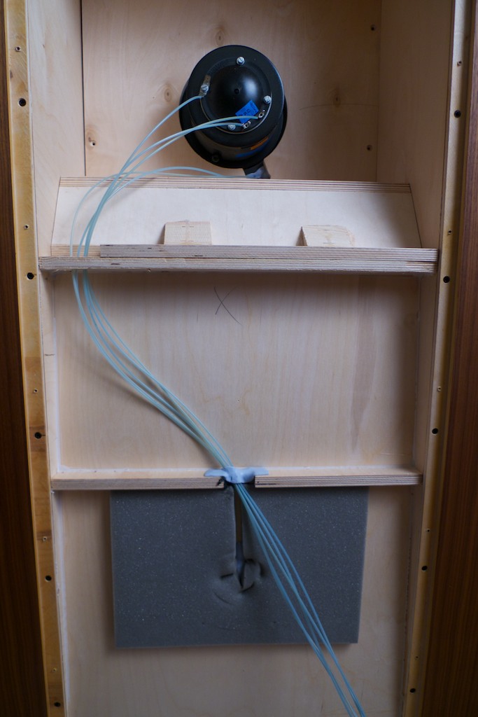
I hooked up the wires to the "OUT" side of the breadboarded Duelund crossover, and then hooked up the Panatela component speaker cables from the amplifier to the "IN" side of the Duelund crossover, and sat down for a quick listen to make sure everything was working right.
Another photo:
More to come shortly - thanks for stopping by!