I can't think of a better way to spend a Saturday than eating wood-fired pizza, drinking some nice Italian & Argentinian wines, and laughing & talking with Pete Riggle and Stephaen Harrell while breadboarding the Duelund-WRSE crossovers. We started with a full set of the Duelund CAST components for the crossover. (seen below sitting on a walnut shelf from my McKinnon media cabinet)
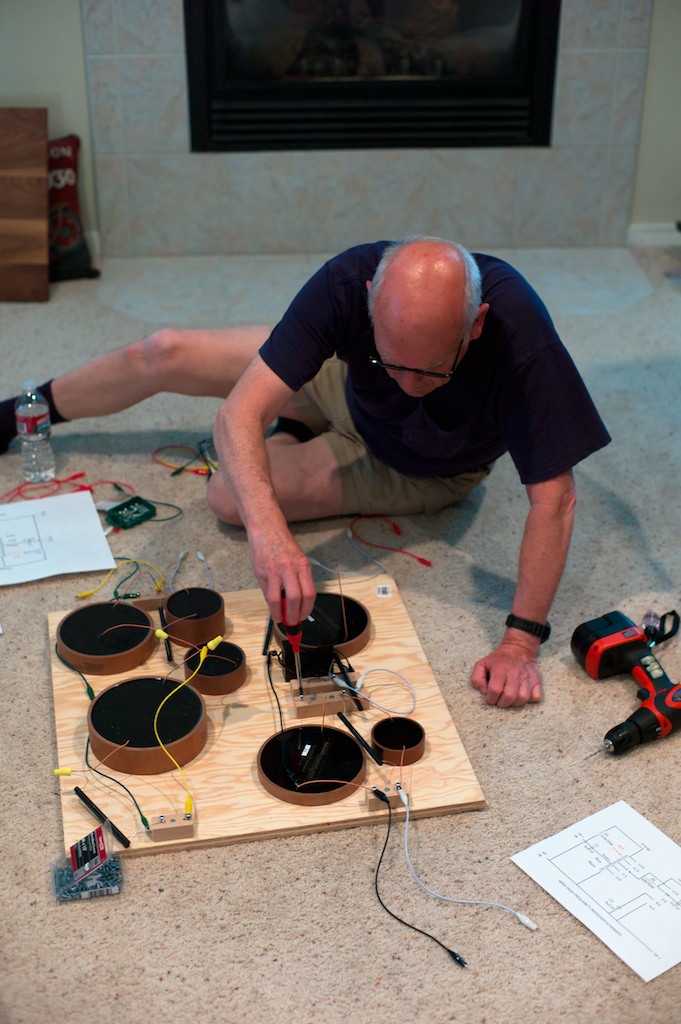
To serve as the base for our breadboard we chose 2-foot squares of plywood. At this point we're not trying to make things pretty, we're just trying to make sure we understand the circuits and how all the components go together. Here's Pete doing some basic layout according to the schematic (below).
I decided I wanted to leave the original WRSE crossovers intact and in place in the loudspeakers, but out of the circuit. That way in the future I can do A-B listening comparisons for the stock Tannoy crossover and the Duelund crossover for the article I'll be writing for Positive Feedback Online. That means I'll be needing a pair of autoformers to complete the Duelund-WRSE high-frequency crossover circuit, so Paul Mills is going to send a pair to use for the project.
If you decide you want to modify your Tannoy crossovers too, you'll probably just want to use the autoformers off your original crossover boards, but if not, then you can order a pair through your local Tannoy dealer. If you don't have a local Tannoy dealer then go to the Tannoy Sales & Service page of the Tannoy website and you should be able to track down someone who can get them for you.
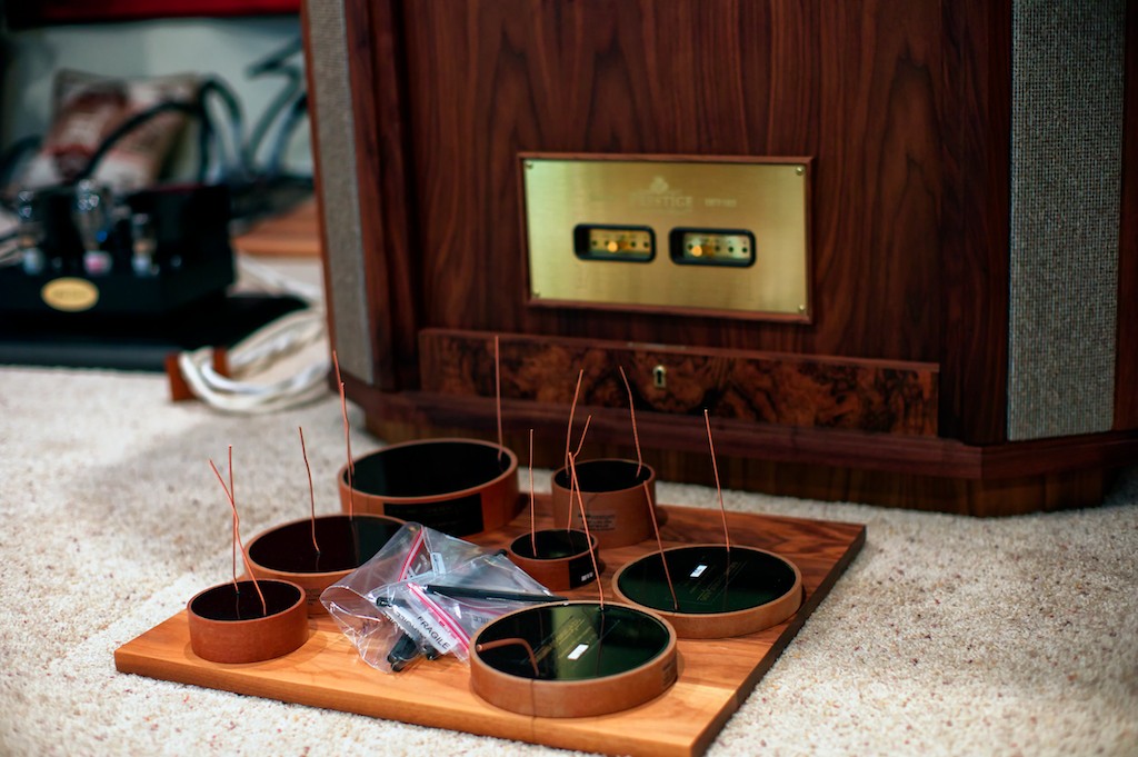
You'll notice that the autoformer is missing from the parts selection, as Paul Mills was so busy getting everything ready for the upcoming Munich Hi-Fi show this week he didn't get a chance to get a set of autoformers shipped out for us (Paul also mentioned that we could expect to see some really cool things from Tannoy in Munich, so now I'm really curious!). So fingers crossed that the autoformers will be coming soon!
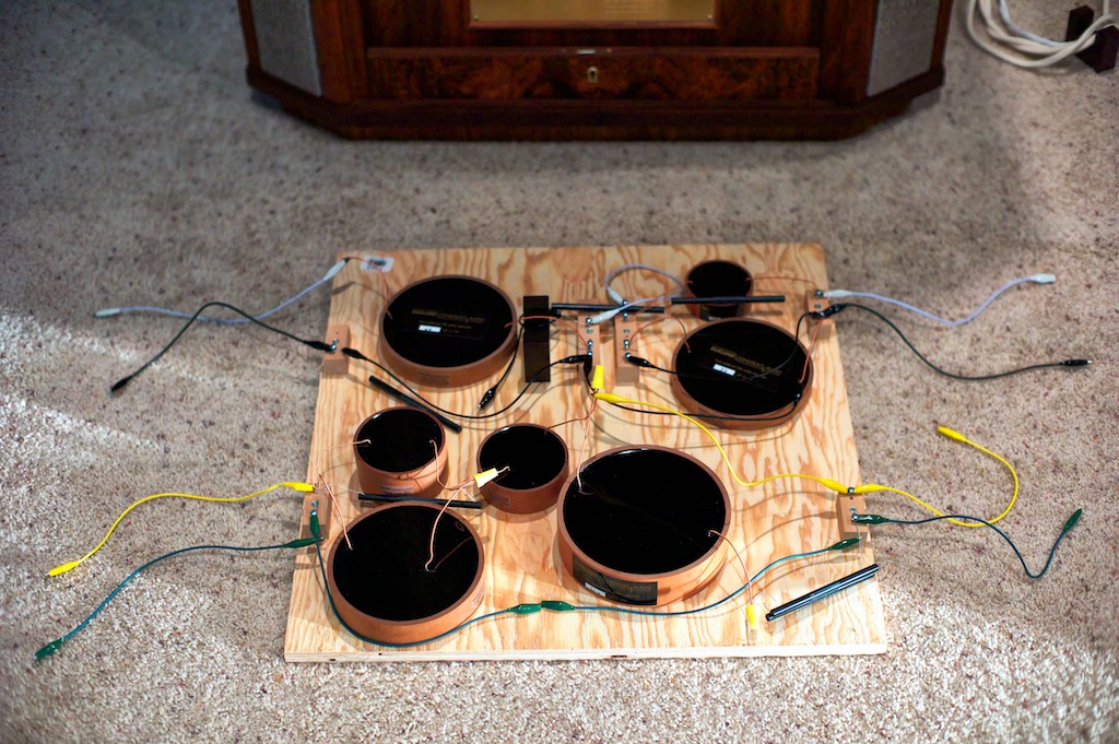
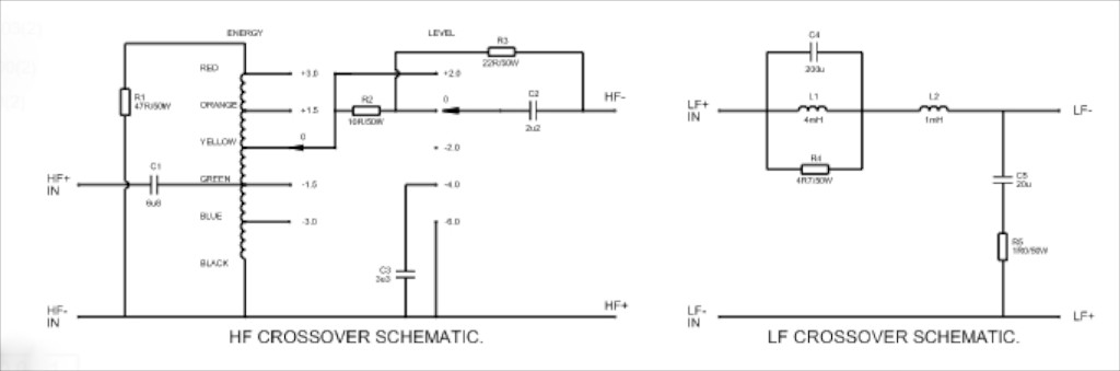
In the bottom half of the breadboard you can see the components laid out for the low-frequency part of the crossover. On the bottom left the green alligator clip represents the LF - IN, and the yellow alligator clip represents the LF + IN, as depicted in the LF crossover schematic above. The top half of the breadboard is the components laid out according to the high-frequency crossover schematic. An Acoustic Revive cable riser is doing duty as a mock autoformer momentarily for the purpose of breadboarding until Paul's autoformers show up.
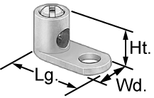
The wires with alligator clips are just being used to help us visualize how things will go together and will not be used as part of the crossover. We are planning on using the wire directly from the Duelund components to make mechanical connections utilizing copper set screw lugs (diagram above), which is a better sounding way of making connections than soldering, and has the added benefit of allowing us to instantly swap components out at any time for comparative purposes for the upcoming article. I ordered straight tongue copper set screw lugs, 14-8 AWG, #10 stud, from McMaster-Carr, part number 6923K61. I ordered 30 of them to get us started, and I'll keep you posted as to how they work out.
If/where we do need to use any hookup wire in the crossover, the plan is to use 20 gauge Neotech solid-core UP-OCC silver wire with a Teflon jacket in the high-frequency section of the crossover, and 14 gauge Neotech solid-core UP-OCC copper wire with a Teflon jacket for the low-frequency section of the crossover, and using WBT crimp sleeves where needed.
Also, we are planning on using the binding post bypass strategy for cable connections from the speaker and amplifier, so each crossover will require 4 pairs of binding posts, or a total of 8. Add 2 more pairs if you want to do the Tannoy ground scheme with binding posts as well. You don't need fancy binding posts with this strategy as they're not in the circuit, they're just used as a clamp to clamp wires and cables together.
Ok, well that's it for now. I've got some really interesting ideas to share with you about preserving the level & energy adjustments of the high-frequency crossover - courtesy of Pete Riggle - but doing it in purist fashion so there is zero signal degradation as there is with the stock setup, but that will have to wait for another post.
Thanks for stopping by! More to come!