

As I've promised in earlier posts, I’m archiving the Duelund-Westminster External Crossover article here at Jeff’s Place so you can find everything in one place for reference purposes (Part 1 - Intro, Part 2 - Breadboarding, Part 3 - Final Design).
The full version of the article was just published in Issue 70 of Positive Feedback Online here so be sure to check it out if you haven’t already.
Here is the next installment of the Duelund-Westminster External Crossover Project, Part 4, describing rewiring the Westminster Royal SEs to get the most out of the Duelund-WRSE external crossovers. Enjoy!
Continued from Part 3:
Rewiring the Westminster Royal SE Loudspeakers
For rewiring the Westminster Royal SE loudspeakers to accept the Duelund CAST external crossovers, Mark Coles was a major source of inspiration on how to best preserve the signal quality coming from the exotic Duelund CAST external crossovers to the WRSEs’ Dual Concentric drivers. To that end Mark suggested eliminating the WRSEs’ internal wiring connectors, the driver connecting plugs, and the binding posts, which all degrade the audio signal to an extant.
At first Mark had recommended that I use the same Neotech wire for the internal wiring of the WRSEs that I had used for the Duelund CAST external crossovers, but after considering the enormous performance improvement I realized with my WRSEs from his Sablon Audio Panatela component speaker cables (which I reviewed in Issue 63 of Positive Feedback Online), Mark suggested we instead use a continuous run of Panatela cables from the Dual Concentric™ drivers to the external Duelund CAST crossovers to see if we could realize a similar performance improvement from using the Panatelas as internal wiring.
Let me say that Mark’s idea of running a continuous set of Panatela component speaker cables from the drivers to the crossovers really appealed to me, and it turned out to be a complete success. While the primary focus of this article is upon the remarkable performance improvement that can be realized by using the Duelund CAST components in the external crossovers for the WRSEs, I want to emphasize that to fully benefit from the Duelund CASTs’ lofty performance potential you’ll want to use the absolute best internal wiring possible, and for my Westminster Royal SE loudspeakers that’s the Panatela speaker cables that Mark has tailored to perfection to match their performance needs.
To get an idea of the sort of performance you can expect by using the Panatela component cabling in the Westminster Royals SEs, I recommend that you go back and read the Panatela review in Issue 63 of Positive Feedback Online where I covered it in detail. Here is a snippet about the Panatela’s performance from that review:
“The Panatela had a rich, luxurious, slightly warm & dark presentation, which at the same time was extremely transparent and high resolution, which I find to be a rather amazing set of qualities, as usually you can have one or the other but not both. This 'darkly detailed' style of presentation is my personal audio Holy Grail, because it not only portrays a musical performance as emotionally engaging, but also as spectacular sonically, which provided an unbeatable combination that left me in an almost constant state of musical satisfaction and amazement.
The Panatela speaker cables portrayed timbral characteristics like textures, colors, and tones & overtones superbly, and in my experience the Panatela is in a class by itself in this regard. The string tone and color in Swan Lake was so naturally & compellingly portrayed that it left me in a state of awe as to its beauty and ability to stimulate an emotive response. The same with Getz/Gilberto, where instrumental timbres (piano, guitar, sax, drums and bass) and Astrud's & Joao's vocals were so beautifully tangible and present that it was intoxicating.
One of the strengths of the Panatela is being able to unravel complex music, like classical music, and present it in its full sophisticated glory. In this regard I think the Panatela speaker cables have no rival. Listen to any one of the Ansermet recordings and I suspect you'll be picking your jaw up off the floor even as I did. This level of musicality combined with this level of sonic sophistication is unrivaled in my experience.”
I was completely blown away by the performance improvement the Panatelas brought to my Westminsters during the review, and using them as internal wiring for the Westminsters yielded similar results times two. Using the Panatela component speaker cables as the internal wiring for the WRSEs was a truly exciting development in the project, and I’d like to thank Mark Coles for suggesting it and providing a set of Panatela component cables to use for the project.
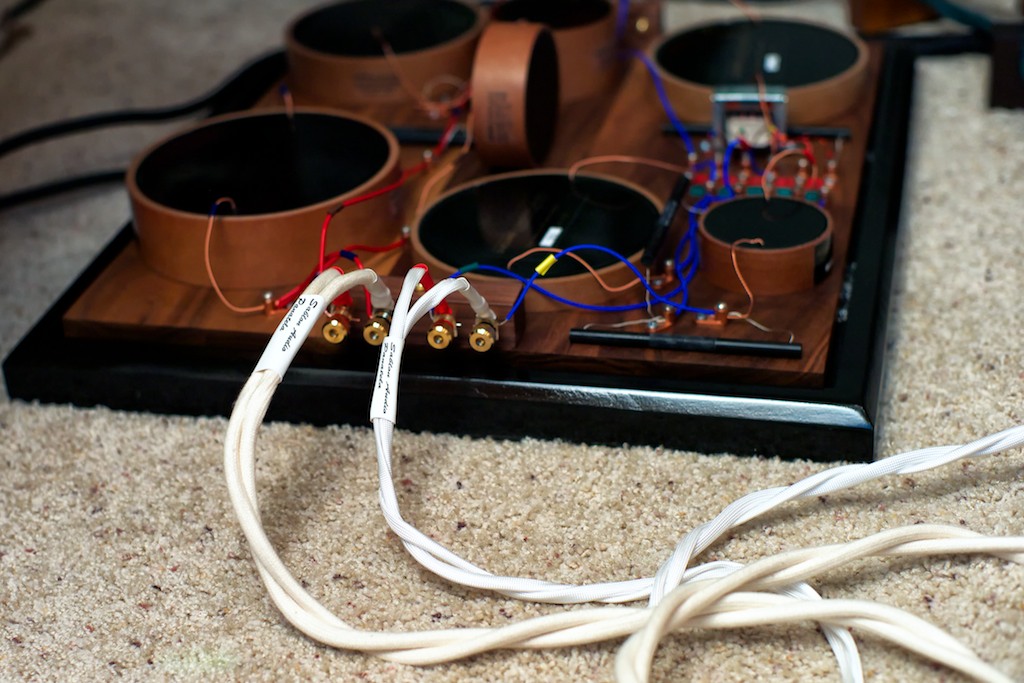
As we get ready to move on, let me remind you what goes into producing a set of Panatelas. Mark custom makes every set of Panatela cables, and builds them up from the bare wire. Mark meticulously voices the Panatela cables using a variety of different conductors and natural dielectrics. As I mentioned in the review, Mark contacted Dr. Paul Mills at Tannoy and got his advice about optimizing the high-frequency Panatela cable run to match the Tannoys Dual Concentric™ high-frequency driver characteristics. Mark doesn't use solder joints that degrade the sound, he uses great connectors, and he meticulously tweaks the design with cryo treatments, anti-oxidants, contact paste and the like. To top it off Mark pre-conditions all of his Panatela cables with an Audiodharma Cable Cooker so there’s no break-in required.
Mark’s approach to making the Panatela cables utilizes the same sort of dedication to perfection as Frederik & Magnus do with their Duelund CAST components, and due to my aforementioned experience I felt confident that Mark’s Panatelas would bring out the very best in the exotic Duelund CAST components. To say I was very excited about the opportunity to use the Panatela component speaker cables as the internal wiring of the WRSEs would be a massive understatement!
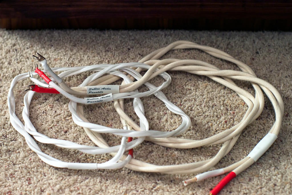
The Panatelas I used for the internal WRSE wiring part of the Duelund-WRSE Project were the very pair of 8-foot Panatela speaker cables I reviewed for Positive Feedback Online back in Issue 63, which Mark Coles repurposed for use as internal wiring by reterminating one end of the Panatela speaker cables to make them suitable to connect directly WRSE’s Dual Concentric™ drivers.
If you decide you want to use Panatelas as internal wiring in your own Duelund-WRSE external crossover project – and I would recommend that – Mark will make you a set of Panatela cables as a custom order to meet your specific needs. Mark told me that the cost would be similar to that of the Panatela speaker cables as they are “the same underlying product with different terminations”. You should contact Mark directly for accurate price quotes on the best length of Panatelas for your project.
To give you an idea of what you’re looking at price-wise to duplicate what I did for this project, the 8-foot pair of Panatela speaker cables used from the low-frequency section of the Dual Concentric™ drivers to the low-frequency section of the external Duelund crossovers retails for $1750 USD. The pair of 8-foot Panatela tweeter cables going from the high-frequency section of the Dual Concentric™ drivers to the high-frequency section of the Duelund external crossovers retails for $1250 USD, and Mark also made me a set of dedicated ground leads to go from the ground on the Dual Concentric™ drivers to the ground on my restored vintage McIntosh MC240/MC30s, which retails for $375 USD. Total Panatela internal wiring cost comes to $3375 USD for an 8-foot set.
I used an 8-feet length of Panatela component cables to provide flexibility for reviewing, so that I could easily move the Duelund CAST external crossovers around to accommodate various electronics during reviews, and also so I could keep them visible during photo shoots. If you have a fixed system you can get by with shorter lengths of cable.
For example, Frank Rogers, a fellow Westminster Royale SE enthusiast who has also done the Duelund-WRSE project for his loudspeakers, told me he successfully used a 5-foot set of Panatelas and that length worked great. Frank also told me he thought he might have got by with a 4-foot set had he placed his crossovers directly behind the loudspeakers.
If you decide you want to do a project like this, I thought it would be handy for you to see every step in the process, so lets go through what I did in detail to rewire my Westminster Royal SEs.
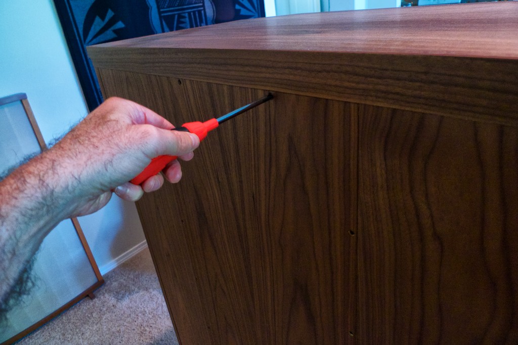
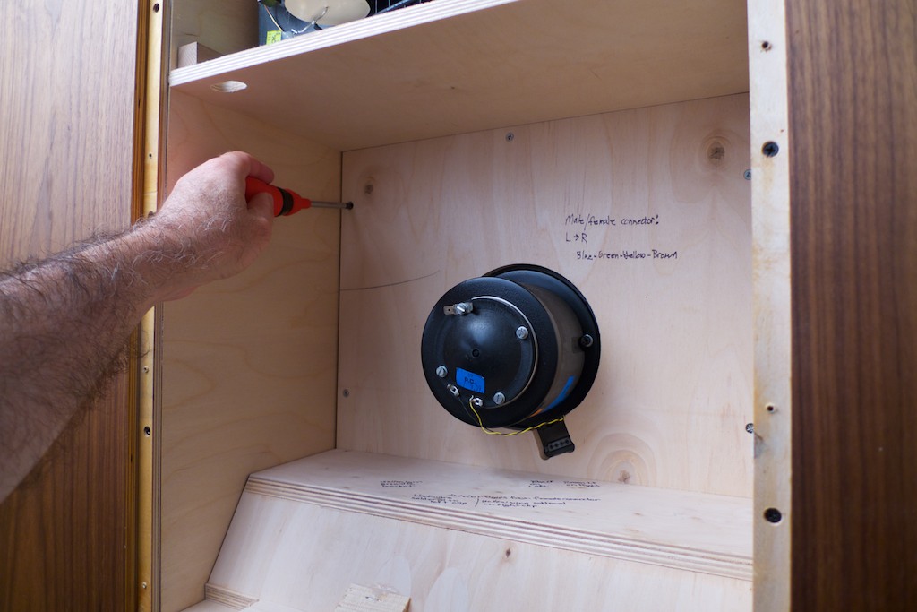
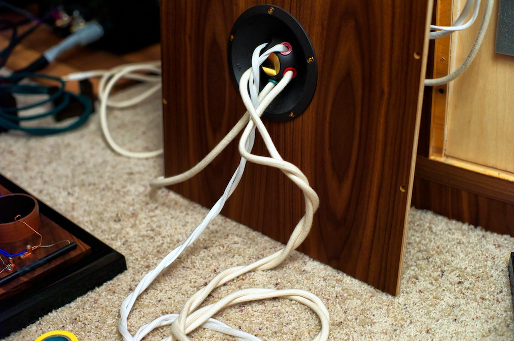
The first step is to open up the big Westminsters by removing the back panel screws with a # 2 Philips screwdriver. After taking out the screws and setting them aside I lifted out the back panel and set it down against the cabinet.
Caution: My back panel came out easy, but Tannoy says the back panel is often a tight fit and warns that owners should not try to pry it out or you could damage the cabinet. Rather, Tannoy says to instead go around the outside of the panel while “thumping it firmly with your fist” until it starts to loosen up and move, then you can lift it out. Good advice to follow to protect your precious WRSEs.
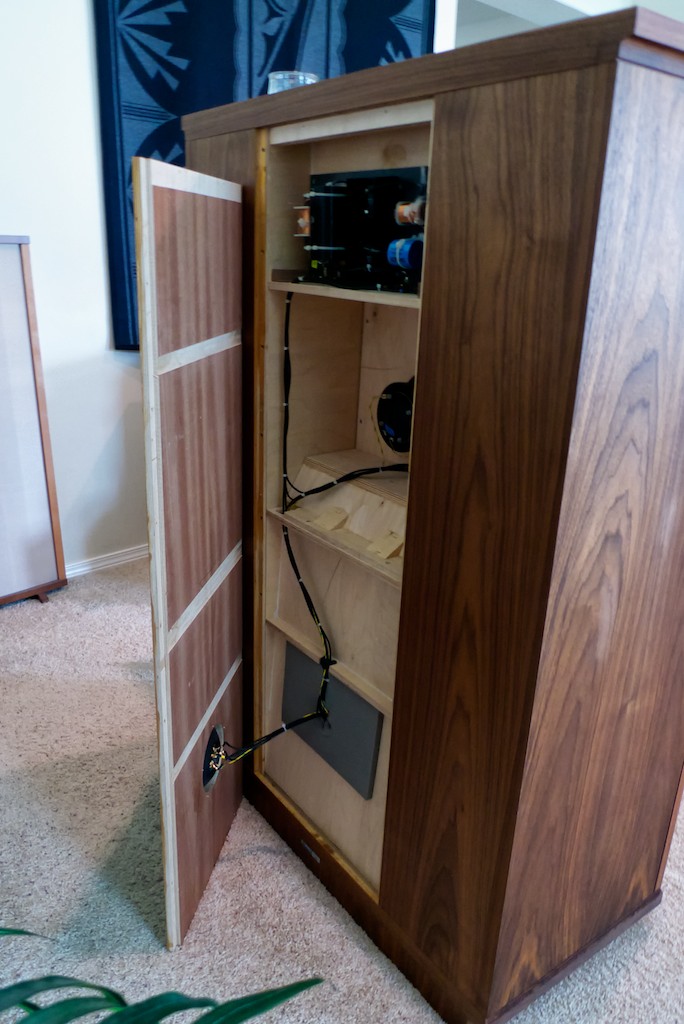
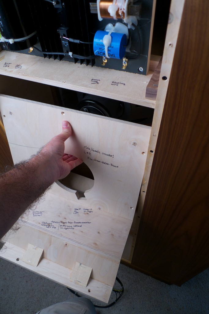
Closer view …
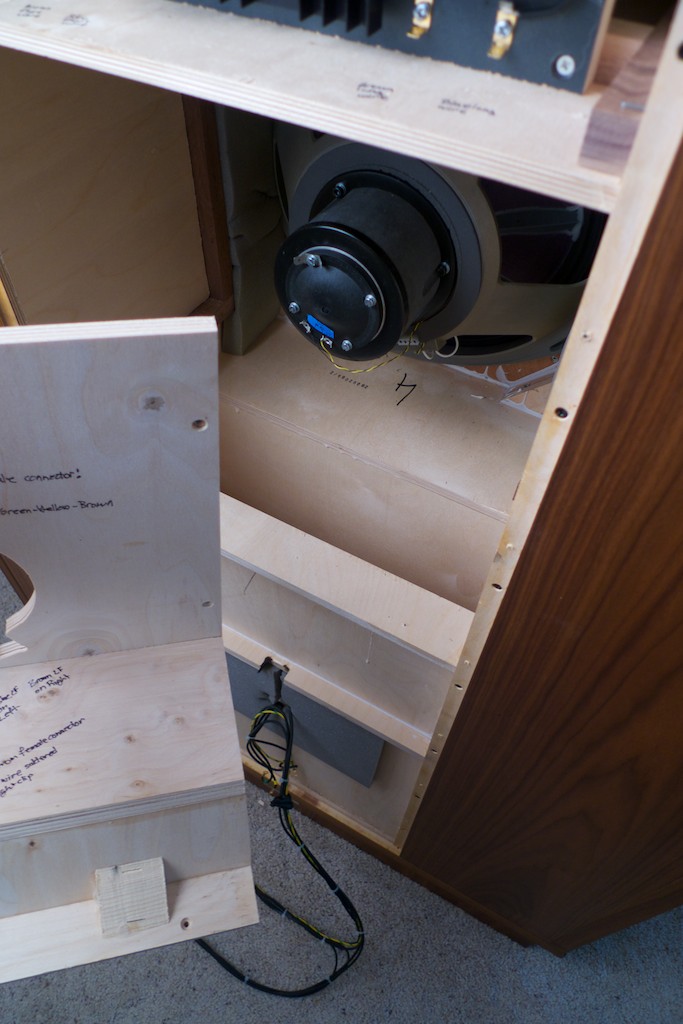
Closer view still …
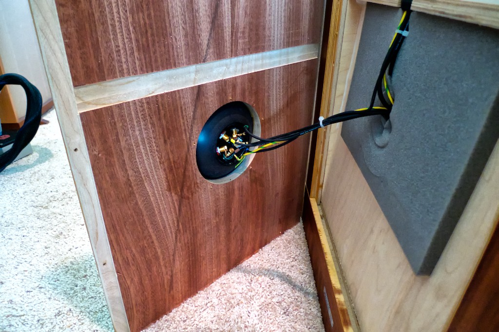
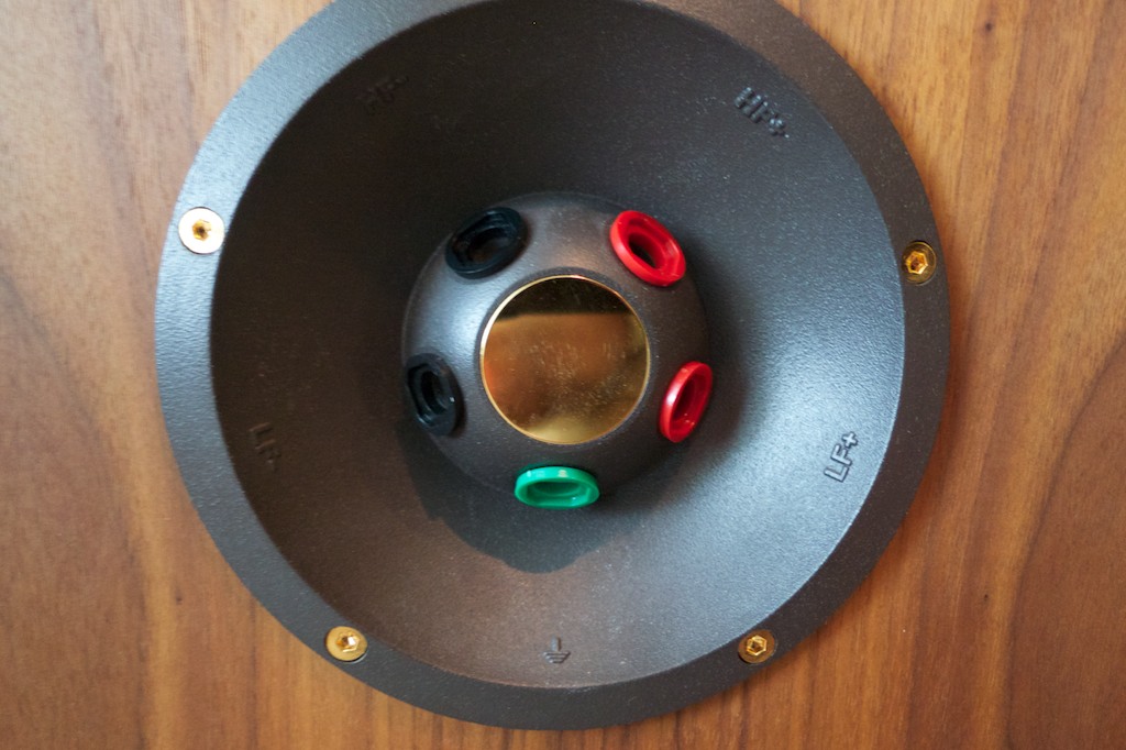
The next step is to remove the WRSEs’ internal wires from the speaker binding posts mounted in the terminal panel.
The internal wires are held to the binding posts with 8mm bolts, so I first loosened the bolts with a 8mm wrench, and then removed the 8mm bolts with a socket to speed the job.
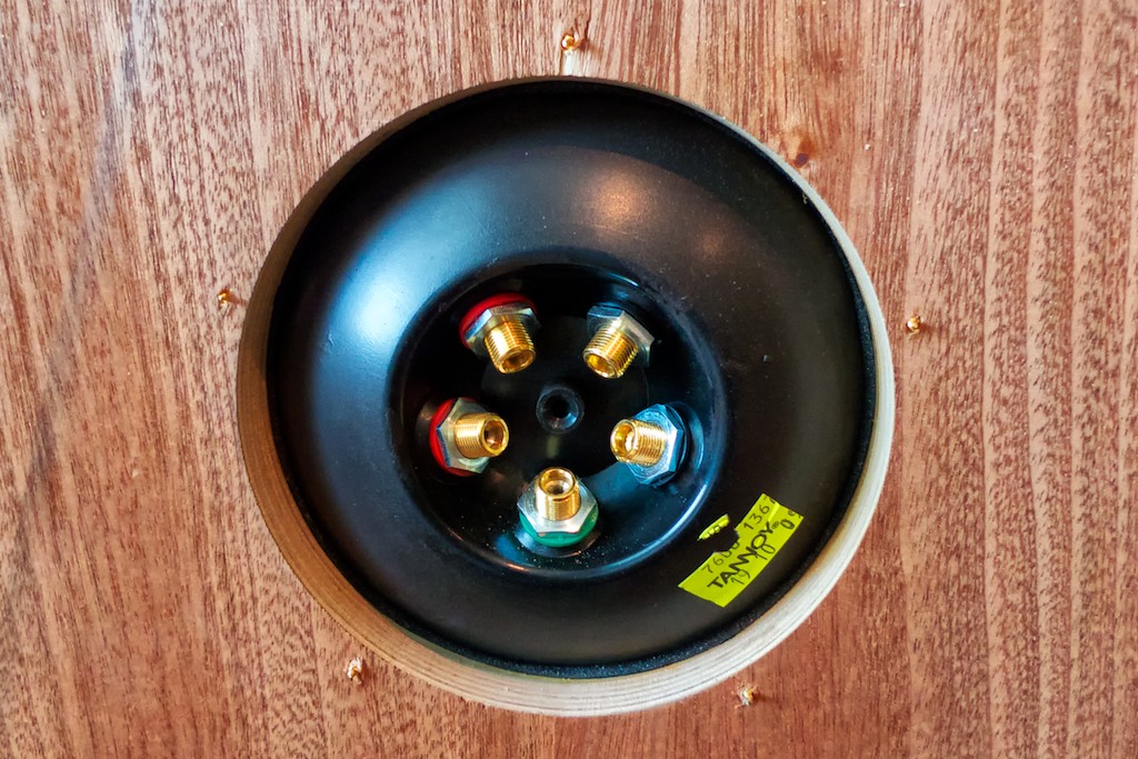
Once the bolts and internal wires were removed, I then removed the nuts holding the binding posts in place, and then removed the binding posts from the terminal panel, allowing me to set the back panel aside to give myself more room to work on the WRSEs internals.
When the binding posts have been removed from the terminal panel the mounting holes are just the right size to thread the Panatela cables through when the time comes!
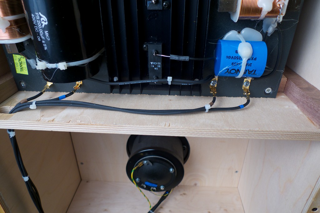
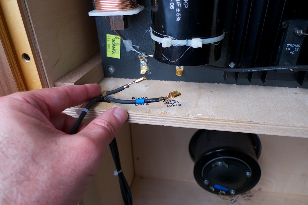
Hint: Before you start unplugging the wiring from the drivers and low-frequency crossovers, be sure to label everything just in case! I wrote directly on the wood inside my Westminster Royal SEs’ cabinets with a Sharpie® to make it clear what went where for future reference.
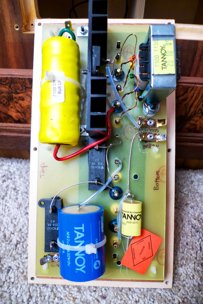
Label the low-frequency crossover according to the wiring color code conventions!
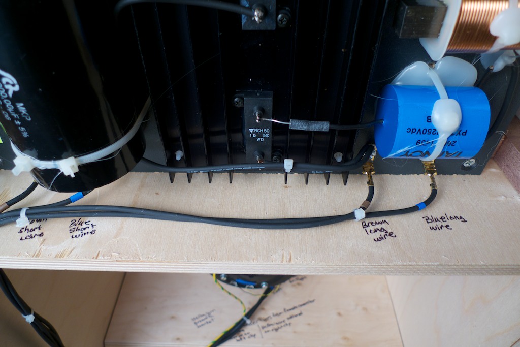
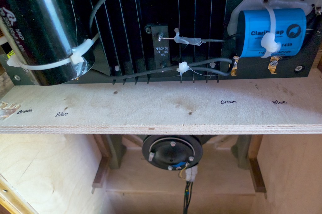
Next I labeled the harness color codes on the inside of the cabinet, as well as the position of the tweeter wires and grounds.
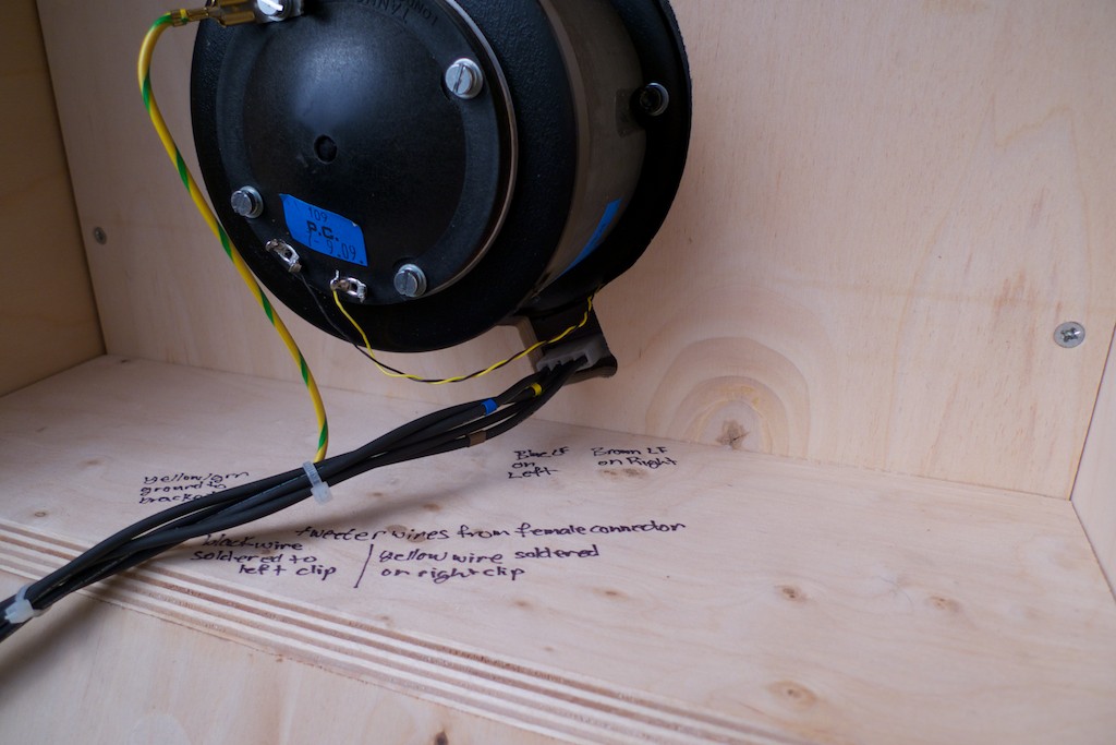
Another view:
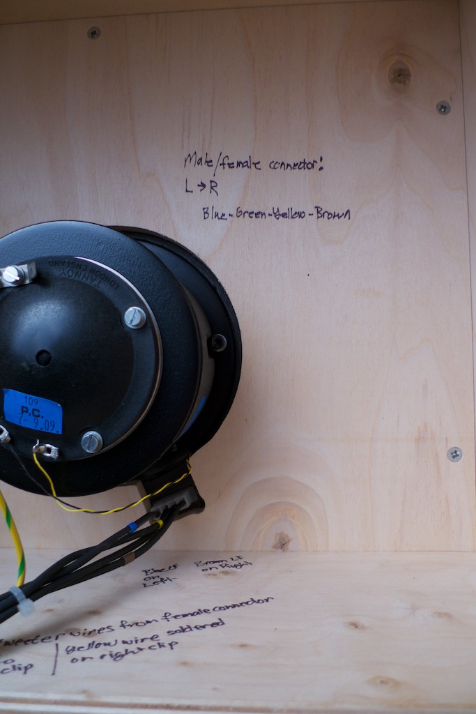
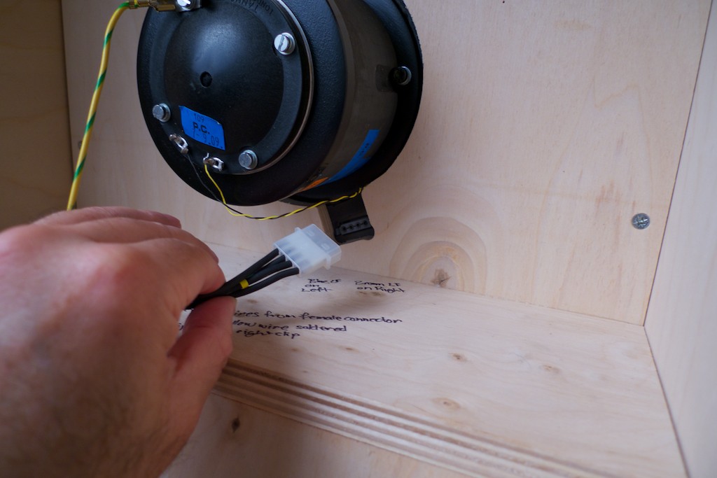
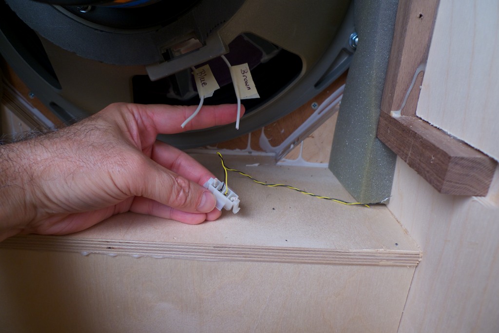
Next I unplugged the drive unit wiring harness male connector from the female connector. It just pulls straight out.
The color-coding scheme Tannoy uses for the internal wiring follows this convention:
Brown: LF +ve
Blue: LF –ve
Yellow: HF +ve
Green: HF –ve (this wire is black from the female connector to the driver)
Green/yellow: Earth
Next unplug the yellow/green ground wire.
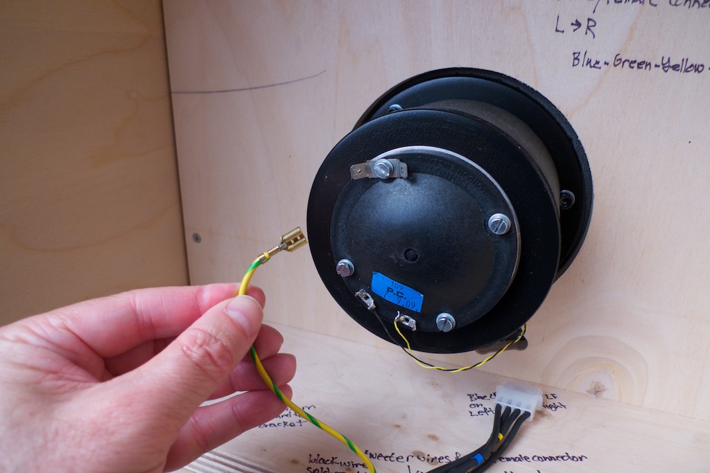
Then unplug the four wires from the low frequency crossover.
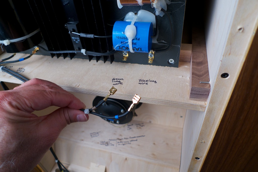
Next I pulled the wires down through their routing holes to get them out of the way for the next steps.
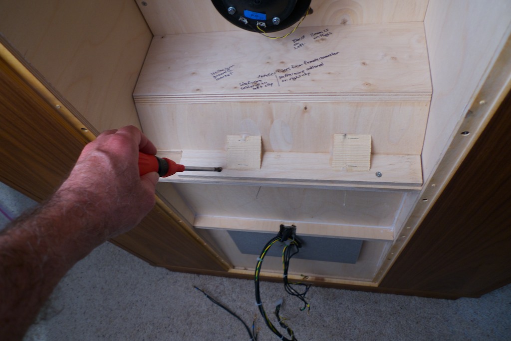
I pulled the wires down through the second routing hole too and let the wire harness rest on the floor. Next I removed the screws that hold the internal plywood structure that seals the bass horn in place with a # 2 Phillips screwdriver. There’s two screws as seen in the photo below and …
… then I removed the 5 screws from around the driver of the internal plywood structure that seals the bass horn.
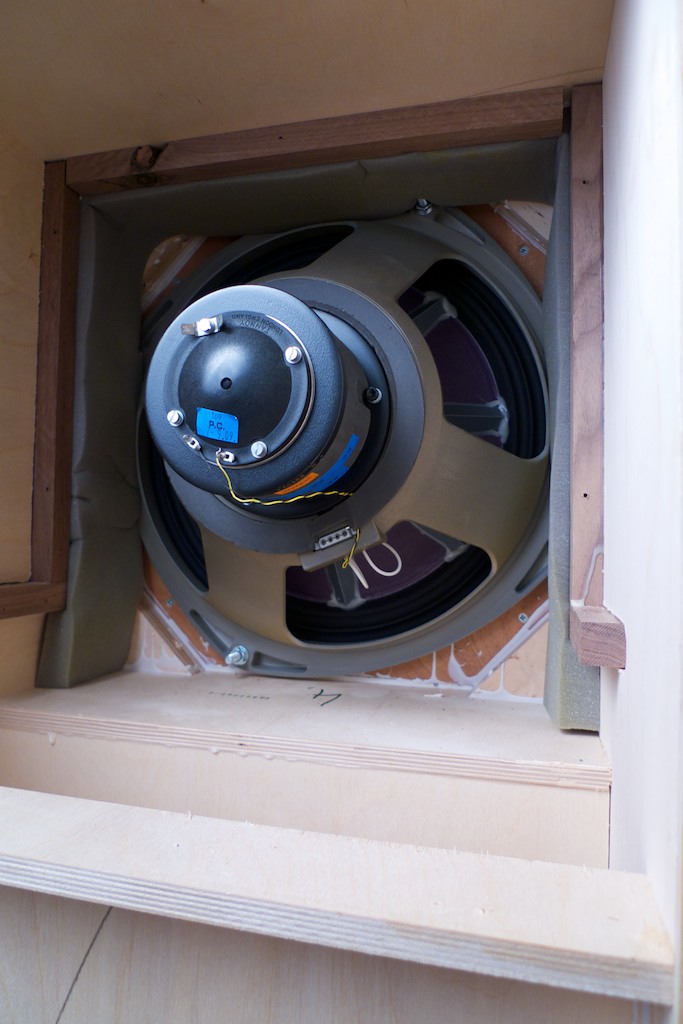
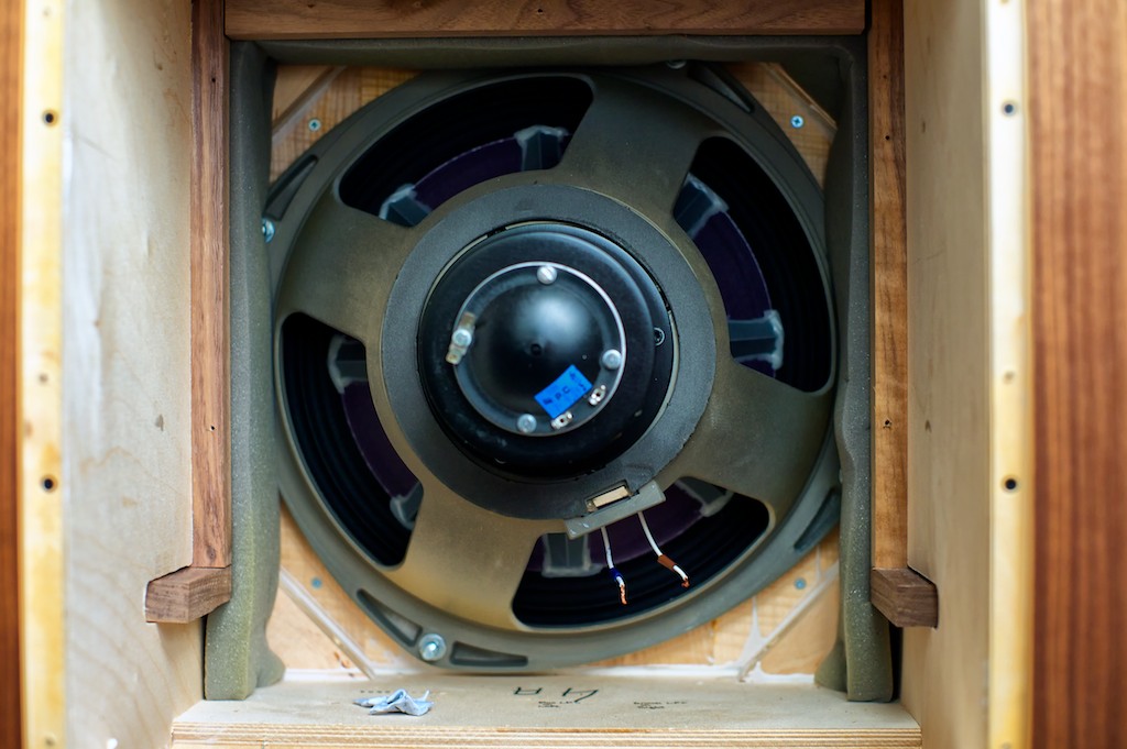
Next I lifted out the internal structure to expose the driver, and then set the inner structure aside.
I’ll connect the internal Panatela wiring direct to the drivers, and then direct to the outputs of the crossover, so I will not be using the stock Tannoy male/female plug connectors, which are said to degrade the sound quality. That way I have only the Panatela wiring in the signal path between the crossovers’ outputs and the driver connections with no intervening connectors.
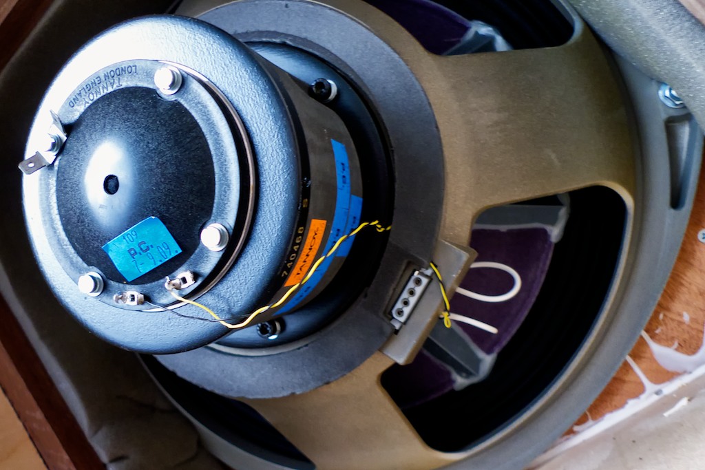
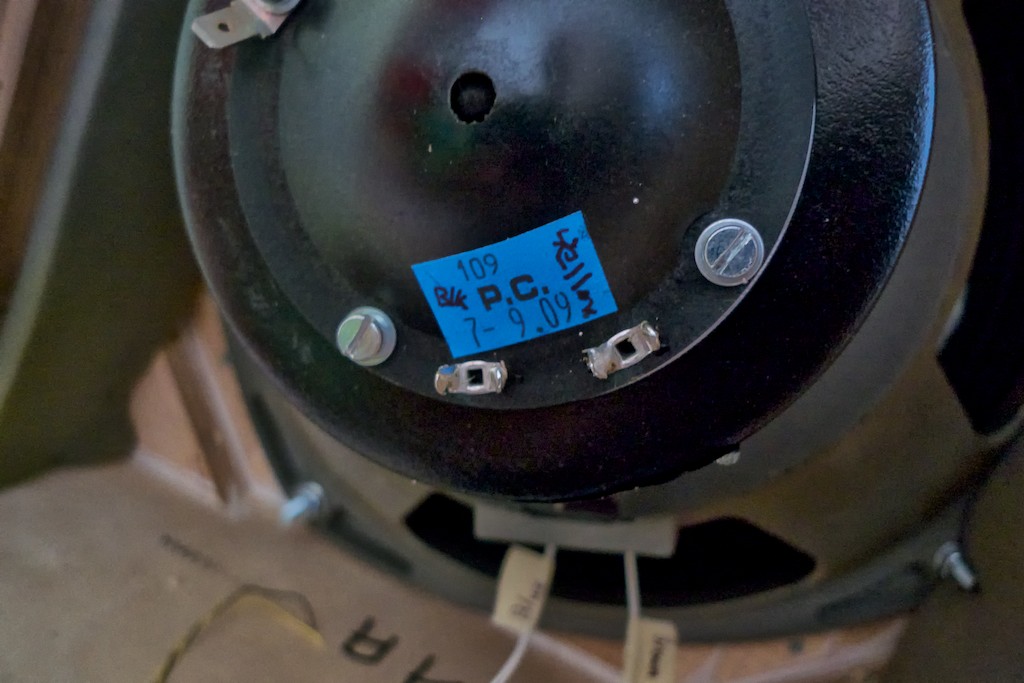
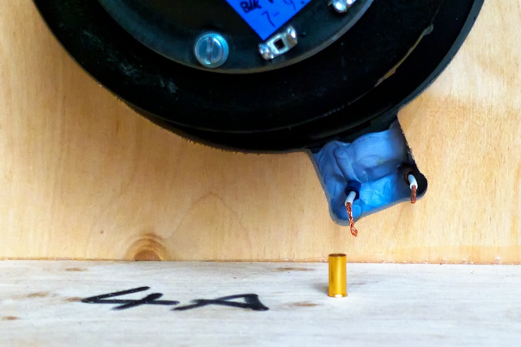
There are two extremely fine wires that go from the female plug connector to the tweeter. There’s a little blue tag on the tweeter endcap, and I suggest that if you’re doing a direct connection of wire to the tweeter driver like I am, that you label it with the wire connection’s color codes. Mine had a yellow wire connected on the right, and a black wire connected on the left. The wires are soldered in place, so I snipped them off to get them out of the way.
Caution: If you choose to desolder / solder the connections for the high frequency wires you need to be extremely quick and cautious about it. The two tabs that the yellow & black high frequency wires are attached / soldered to are mounted on a driver endcap that is made of plastic (the one in the photo with the 4 screws holding it in place). If you heat the tabs too long with a soldering iron you’ll melt the plastic. This could wreck your day as the endcap has micro-electrical connections deposited in it in high-tech fashion, and it is part of the tweeter assembly. If you melt it you will likely destroy it. That means you’ll have to order new ones. They’re probably expensive. Be careful!
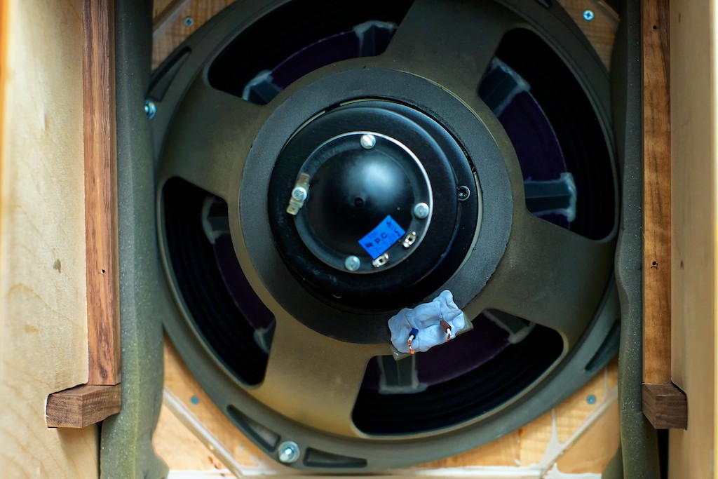
Then I removed the female plug connector from drivers frame. The connector has two little plastic prongs that you have to push in to get clearance so you can push it out (I used a small screwdriver).
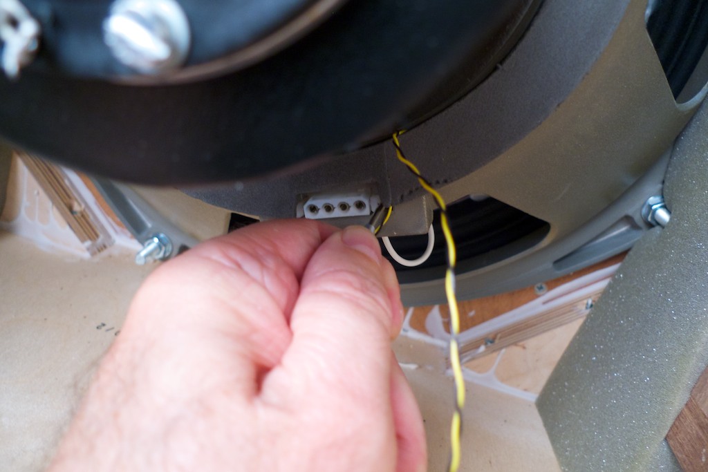
Then I pulled the fine tweeter wires through to free them from the opening.
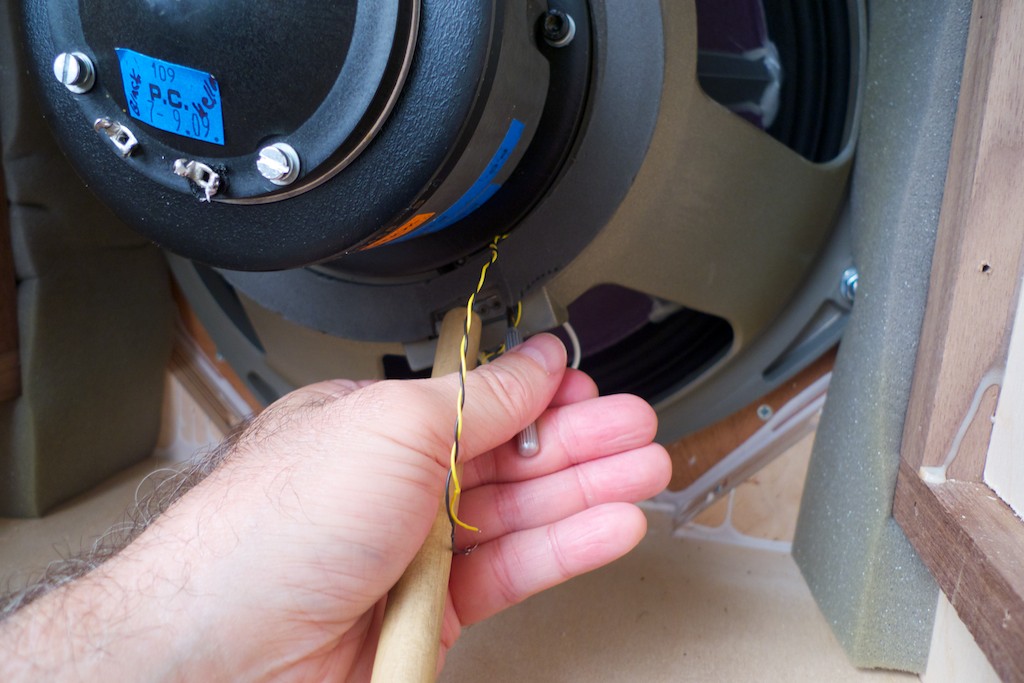
I then pushed the female connector out using the handle end of a wooden spoon (use something non-magnetic or it’ll be drawn into the powerful magnet of the driver, which is a no-no). Note the color-coding and label the wires. Mine had blue (LF -) as the left wire and brown (LF +) as the right wire.
Now it was time to go to work on the high frequency crossover located in the front of the Westminster’s cabinet. On the front of the cabinet I removed the 2 brass adjustment screws and set them aside.
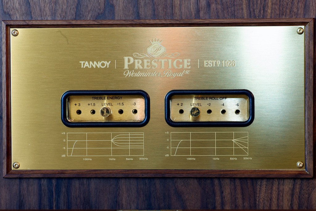
I then removed the four 2.5mm hex screws holding the brass trim place in place, pulled out the plastic cups, and then removed the trim plate and set it aside.
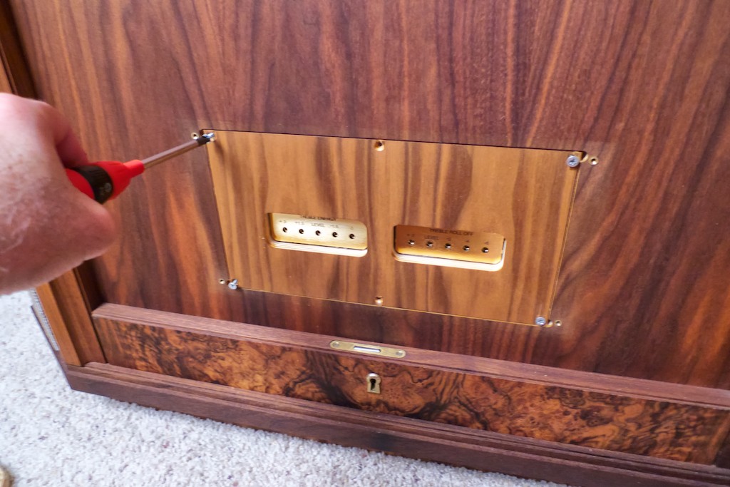
I then removed the 6 wood screws holding the wooden panel and withdrew it to reveal the HF crossover assembly.
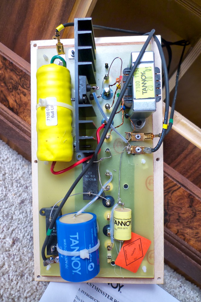
I marked the yellow (soldered) and green (press fit) positions on the circuit board by the autoformer with a permanent marker in case I wanted to re-install the stock cable set, so I could remember what went where. I taped the green and yellow wires together and labeled them “bottom by the autotransformer”.
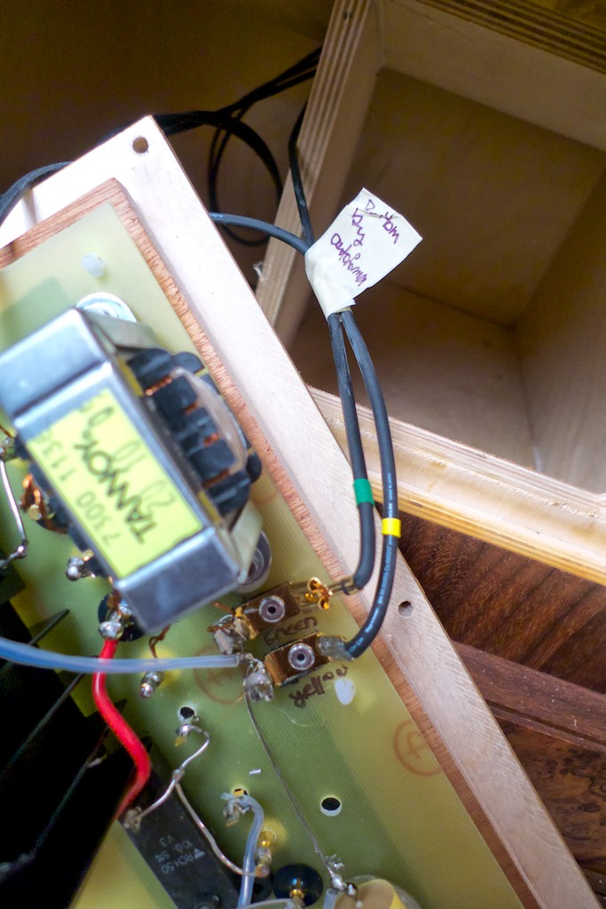
I unplugged the green wire from the circuit board, and then I de-soldered the yellow wire. I then labeled the green (soldered) and yellow (press fit) positions on the top of the circuit board with a permanent marker, and then de-soldered the green wire and unplugged the yellow wire. I taped the two wires together and labeled them “top of the circuit board”.
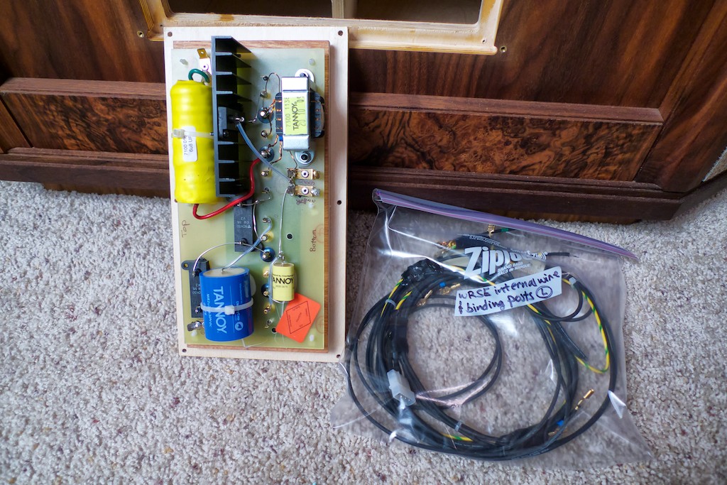
I then pulled the internal wiring harness out through the back of the speaker and placed it in a plastic bag labeled “WRSE internal wire & binding posts Left” and set it aside in case I need it later.
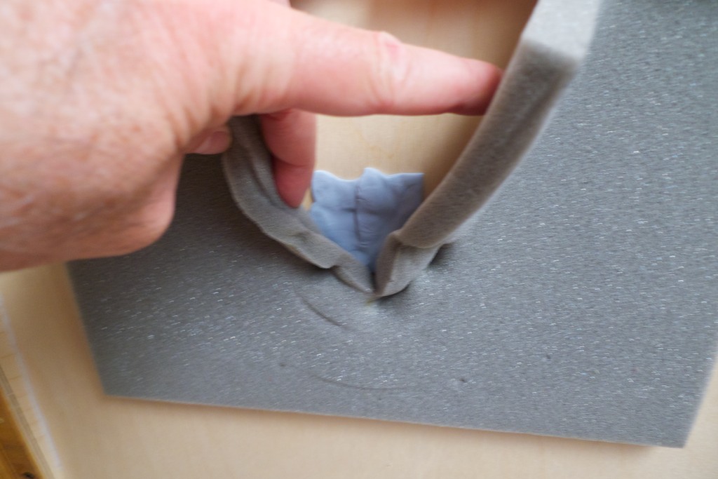
I reinstalled the now disconnected HF crossover back into the cabinet, put back on the trim plate, inserted the plastic cups, and put the selector pins back in place. I then went around back and sealed the wiring harness hole in the back of the horn with Blu-Tack.
Another photo.
I labeled the wires with the Peavey color-coded microphone tape so I wouldn’t get them mixed up.
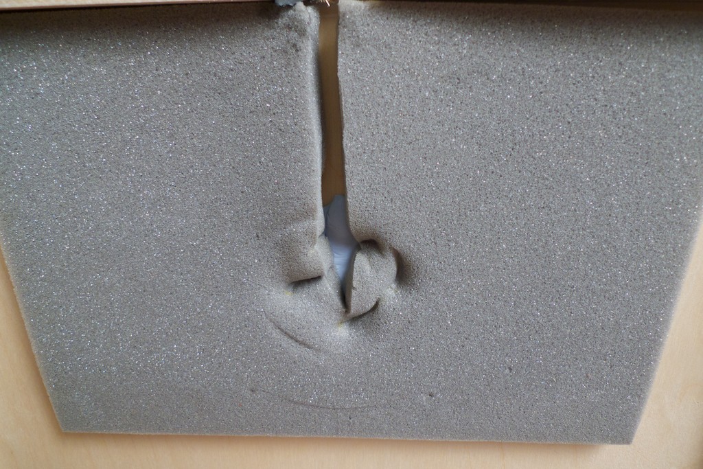
I then pulled the low-frequency wires through the connector hole and then sealed the hole with Blu-Tack. Then I set the internal plywood structure that seals the bass horn and the driver back in place.
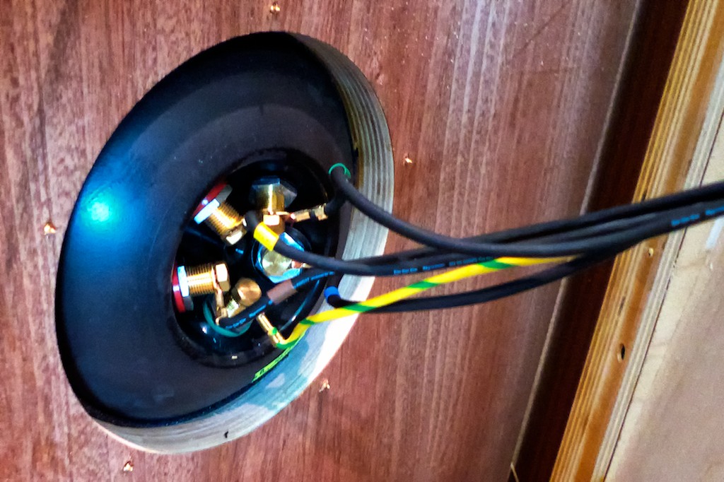
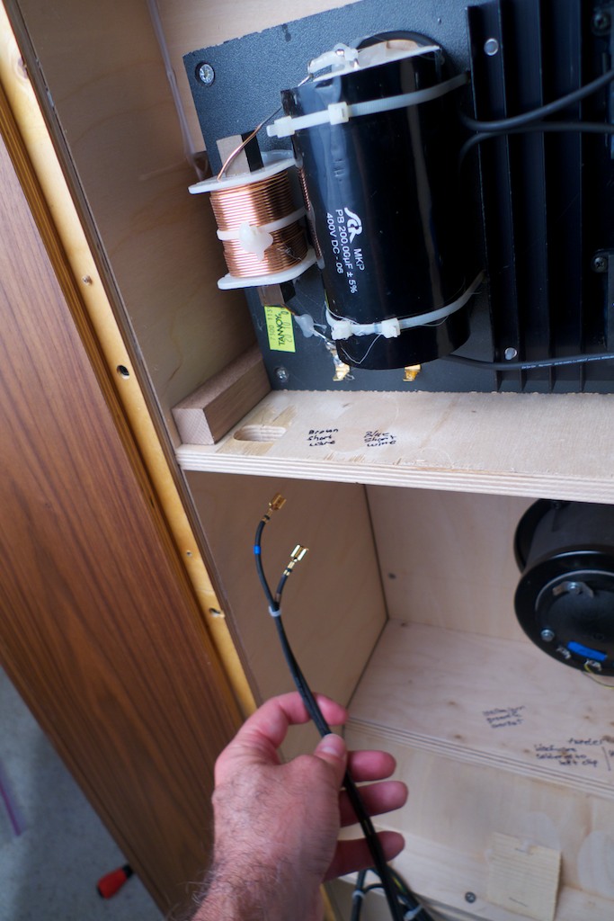
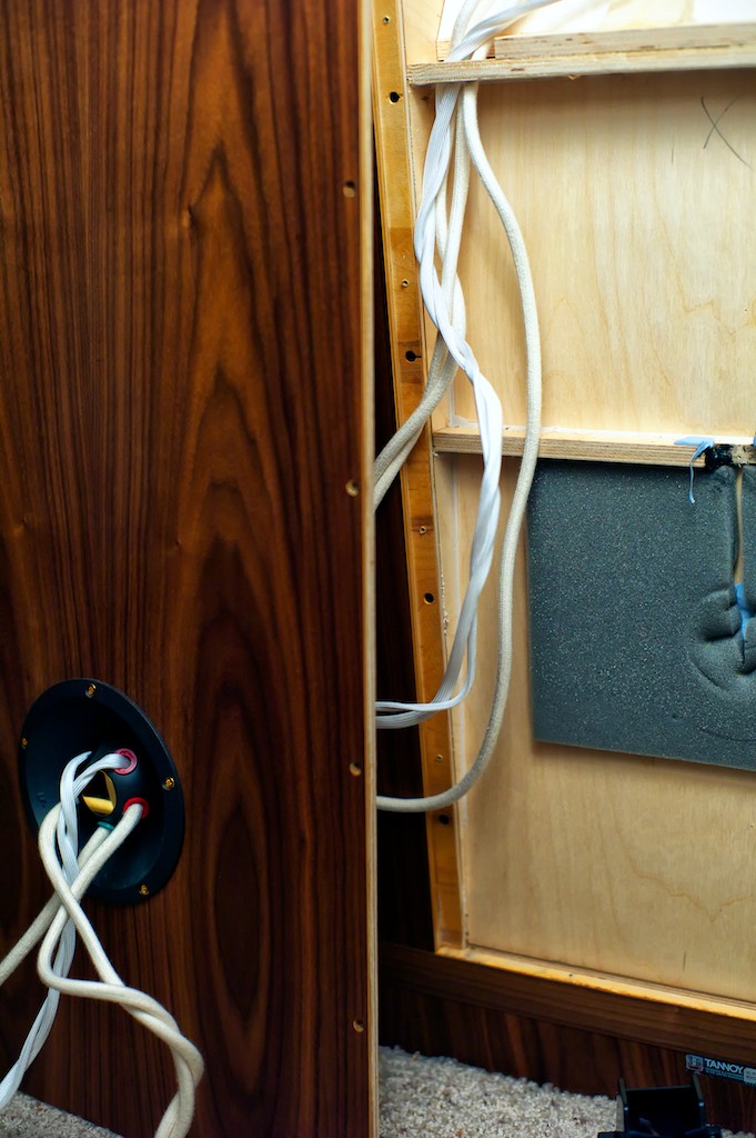
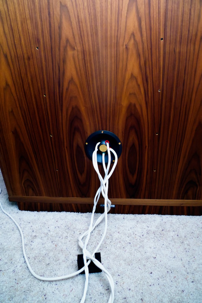
The Panatela low & high-frequency cables sets are shrink wrapped on the crossover end, so I reverse routed them from the external Duelund crossover through the binding post holes in the Westminster Royal SEs.
Through the binding post holes in the Westminster Royal SEs …
… and up through the cabinet routing channels.
As a refresher, the color-coding scheme Tannoy uses for the internal wiring follows this convention:
Brown is LF +ve (this is the red leg of the Panatela low frequency cable), blue is LF –ve (this is the white leg of the Panatela low frequency cable), yellow is HF +ve (this is the red leg of the Panatela high-frequency cable), green is HF –ve (this is the white leg of the Panatela high-frequency cable), and green/yellow is Earth.
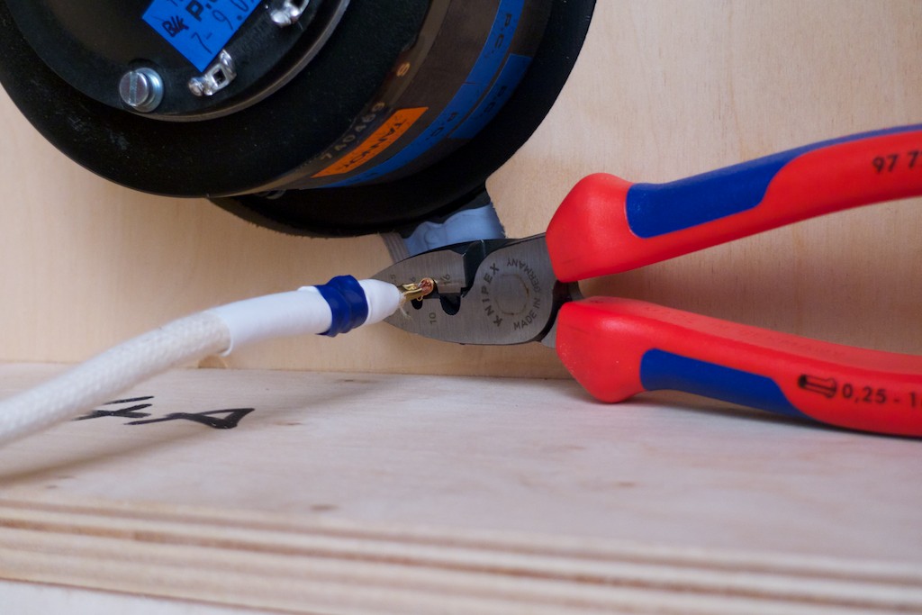
I connected the low frequency cables to the driver leads with WBT 8 AWG crimp sleeves.
The blue LF –ve lead from the driver is crimped to the white leg of the Panatela low frequency cable.
Crimping …
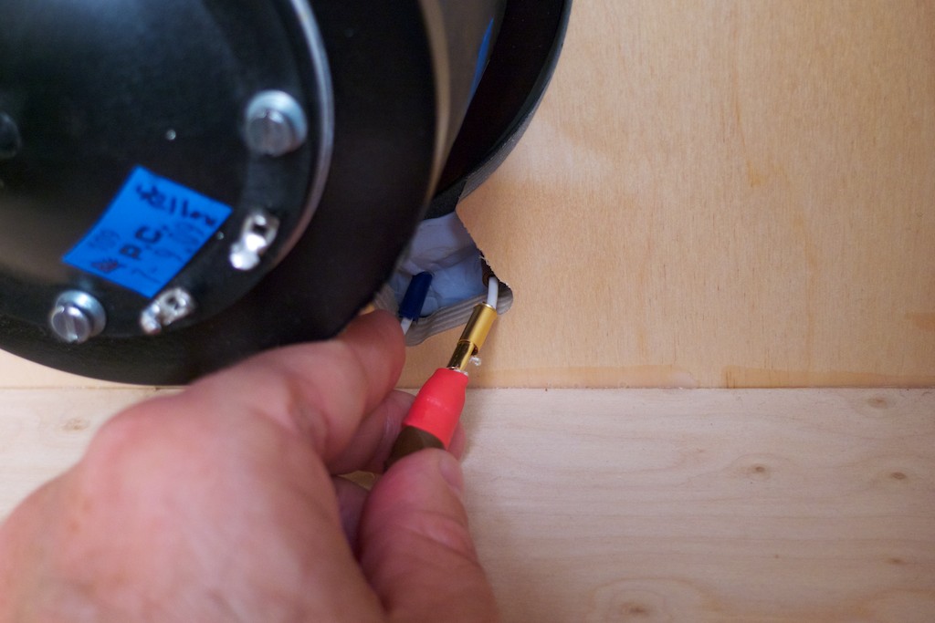
Then the brown LF +ve lead from the driver is connected to the red leg of the Panatela low frequency cable …
Next I connected the Panatela ground using a dab of WBT silver solder …
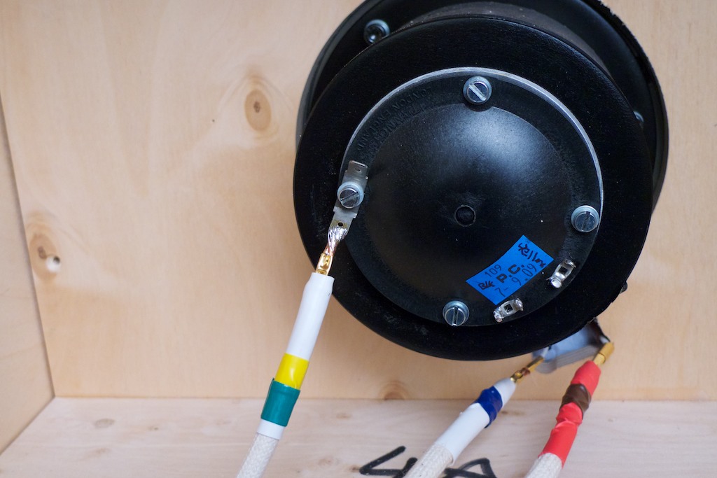
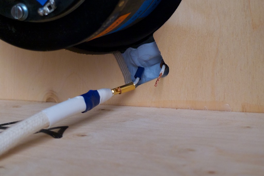
Next I soldered the Panatela HF leads with a dab of WBT silver solder …
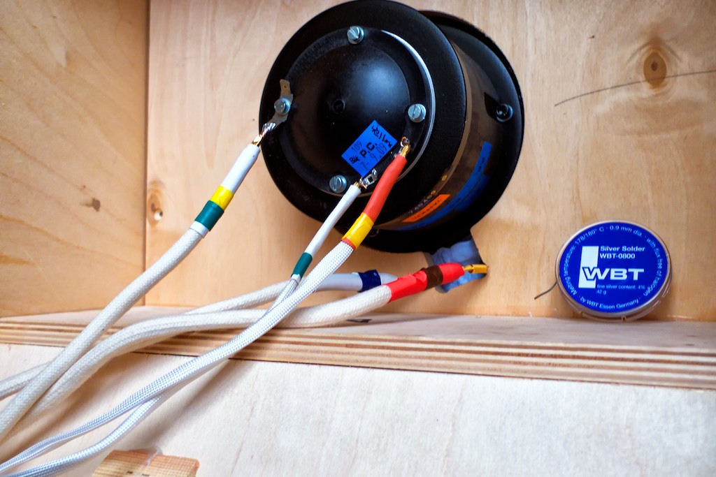
After I got the Panatela cables attached to the driver, I tightened down the internal plywood structure that seals the bass horn and the driver, then secured the cables with a little Blu-Tack, and put the back panel back in place on the WRSE.
My initial fears about my ability to upgrade my Tannoy Westminster Royal Special Edition loudspeakers’ crossovers with the premium Duelund Coherent Audio CAST components turned out to be unfounded, and it turned out to be much easier and more straightforward than I had presumed.
I couldn’t be more delighted with the outcome of the Duelund-Westminster external crossover project - the Duelund CAST crossovers turned out spectacularly good!
Next up will be Part 5 with a review of the results.
Thanks for stopping by!