As I promised in earlier posts , I'm archiving the Duelund-Westminster External Crossover article here at Jeff's Place for reference purposes (Part 1, Part 2). The full version of the article was just published in Issue 70 of Positive Feedback Online here so be sure to check it out if you haven't already.
Here is the next installment of the Duelund-Westminster External Crossover Project, Part 3, describing building the final version of the Duelund CAST external crossovers for the Westminster Royal SE loudspeakers. Enjoy!
Continued from Part 2.
The Final Version of the Duelund CAST External Crossovers
Once the breadboarding of the Duelund CAST external crossovers was complete, I began building the final versions according to the following steps:
- Build the vibrational energy dissipation platforms to mount the Duelund CAST crossovers on.
- Install the Duelund CAST components and Tannoy autotransformers from the breadboards onto the vibrational energy dissipation platforms.
- Use straight tongue copper setscrew lugs from McMaster-Carr for mechanical connections of the wires on the crossover boards.
- Use 20-gauge Neotech solid-core UP-OCC silver wire with a Teflon jacket to wire the high-frequency section of the crossover.
- Use 14-gauge Neotech solid-core UP-OCC copper wire with a Teflon jacket to wire the low-frequency section of the crossover.
The inspiration for the final chassis design for the Duelund CAST external crossovers came from the creatively brilliant Mr. Ken Ishiguro of Acoustic Revive fame, whose innovative applications of physics, materials science, and audio engineering principles to his high-performance Acoustic Revive audio products never fail to amaze me in their cleverness and effectiveness in enhancing the performance of my audio system. I chose to base the chassis for the Duelund CAST crossovers on concepts related to the Acoustic Revive RST-38 Quartz Under-Boards I reviewed in Chapter 7 of The Acoustic Revive Chronicles, which are my favorite audio stands/platforms.
As I described them in the review, the Acoustic Revive RST-38 Under-Boards are stands, or more correctly, vibrational energy dissipation platforms, to place your audio equipment upon. The RST-38 Under-Boards are designed to quickly route vibrational energy away from audio components and dissipate it. They feature a composite wood chassis that is filled with quartz granules, upon which a birch plywood top plate is placed to sit components upon. The idea behind using quartz fill in the chassis of the RST-38 Under-Boards is to harness the piezoelectric properties of quartz to dissipate vibrational energy, thereby improving the sound of Hi-Fi electronics placed upon them. Acoustic Revive says that vibrational energy from a component travels through the top board to the quartz filling where it is dissipated, and conversely that vibrational energy coming up through the floor or equipment into the Under-Board’s chassis is also transferred to the quartz and dissipated.
I would have built the Duelund crossovers directly onto the RST-38s if they were big enough, but they weren’t. The massive size of the Duelund components means that I needed the bases for the crossovers to be 20.5-inches by 18.5-inches, and the RST-38′s 17-inches by 13-inches was just too small to accommodate the king-sized Duelund CAST components.
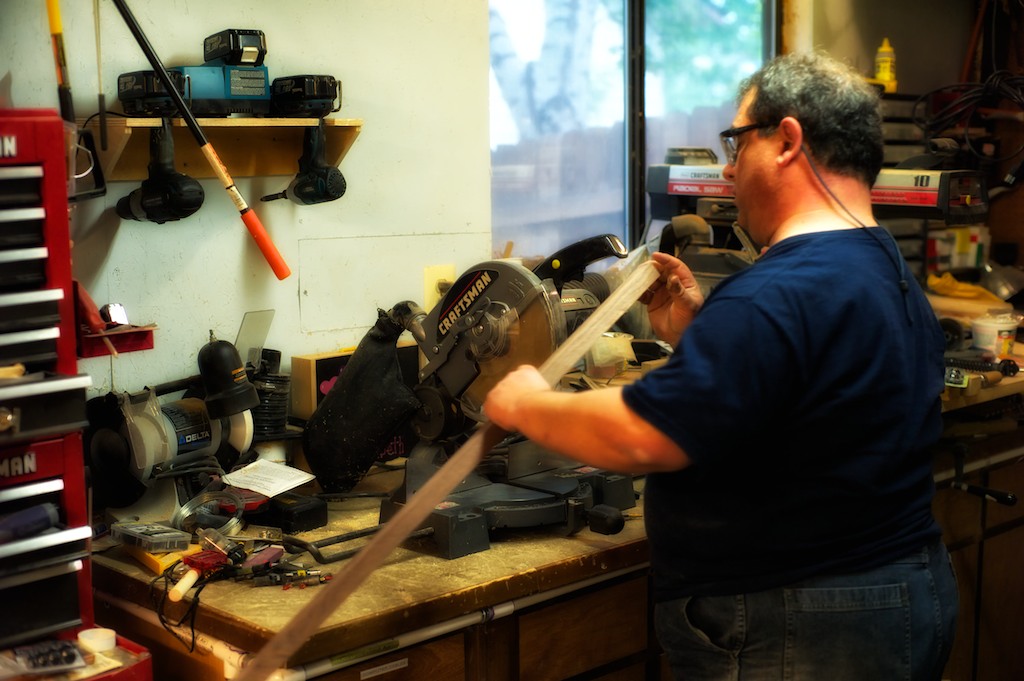
My friend and colleague, Dave (Dave Biancosino, Answers in Art), who is also an expert woodworker, helped me develop and build the final chassis for the outboard Duelund CAST crossovers. After we had the basic design planned out we went into Dave’s woodworking shop to get the chassis started.
Instead of the composite wood chassis and birch plywood top plate of the RST-38, for the Duelund crossovers I wanted to try a tonewood approach (tonewoods are woods used to construct musical instruments, which I thought was quite fitting in this case): a maple frame with a birch ply base, and a solid walnut top plate.
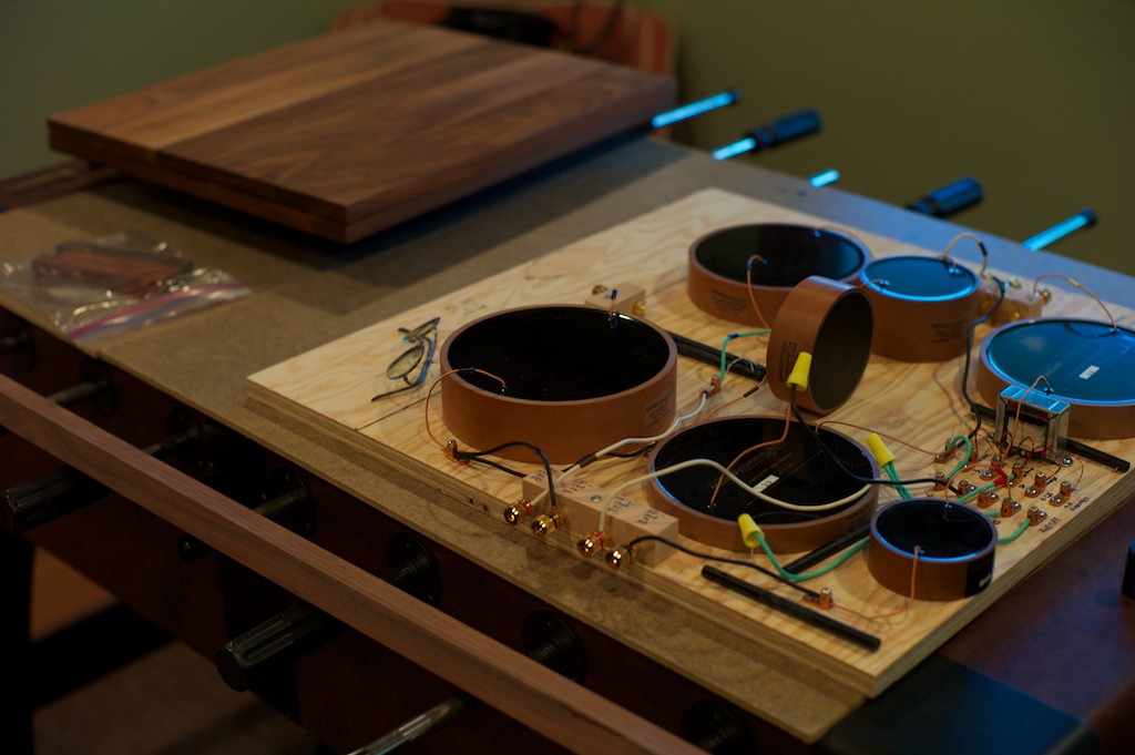
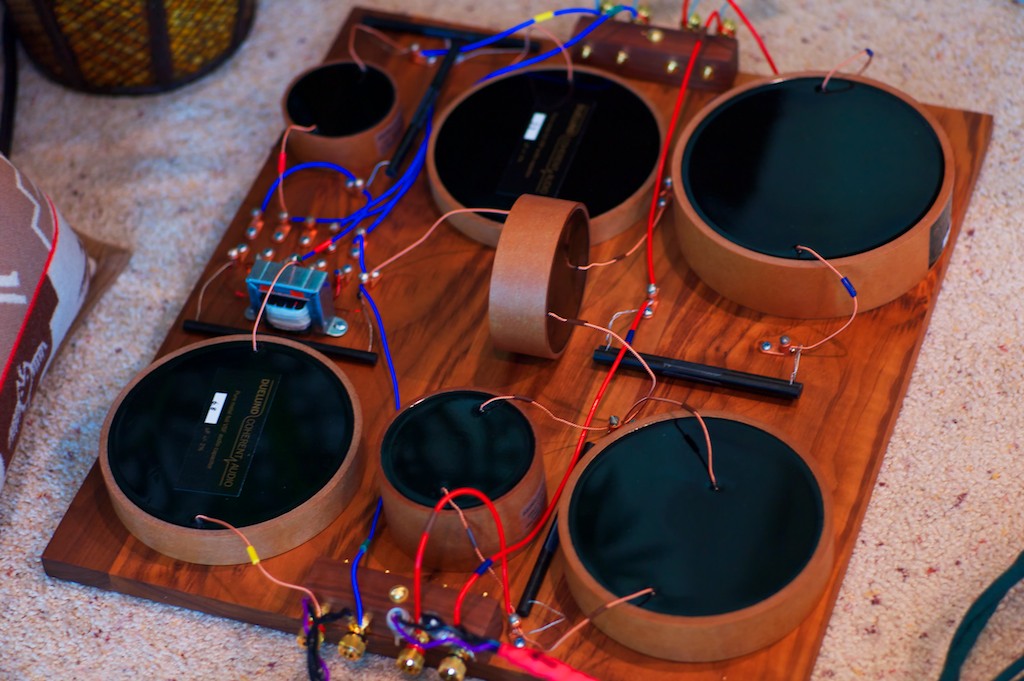
In the above photo you can see the Duelund breadboard crossover in the foreground, and the walnut top plates in the background.
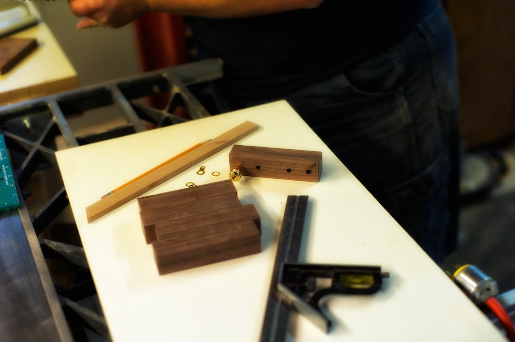
The first thing Dave did was to make the terminal blocks that the binding posts would be mounted to (below), which would then be attached to the walnut top plates.
Then we got started on building the maple frames to fit the dimensions of the 18.5-inches by 20.5-inches walnut top plates, which gave us the needed room for mounting the king-sized Duelund components.
Dave thought it would look nice to use a black ink stain on the maple frames to give the isolation platforms a complimentary finish to that of the Duelund CAST components, which I thought was a particularly cool idea.
After Dave did the glue-up and sanding of the frames, he used an India ink dye to stain the wood. Dave said, “Although any stain or dye would work, to get a jet black finish, India ink or a black acrylic would be needed. The acrylic would not show the grain as well, however.”
After Dave did the dyeing with the India ink, he did a light sanding because the ink is water based and will raise the grain a bit. Dave chose a clear gloss wipe-on polyurethane finish and put 6 coats on the frame. Dave lightly sanded between each coat with progressively finer paper each time to give a beautifully smooth finish.
Dave told me, “Although the bottom will not be seen, it’s important to at least put a coat or two of finish on it as well to eliminate the possibility of warping. You want moisture content of the wood to be the same throughout the wood.”
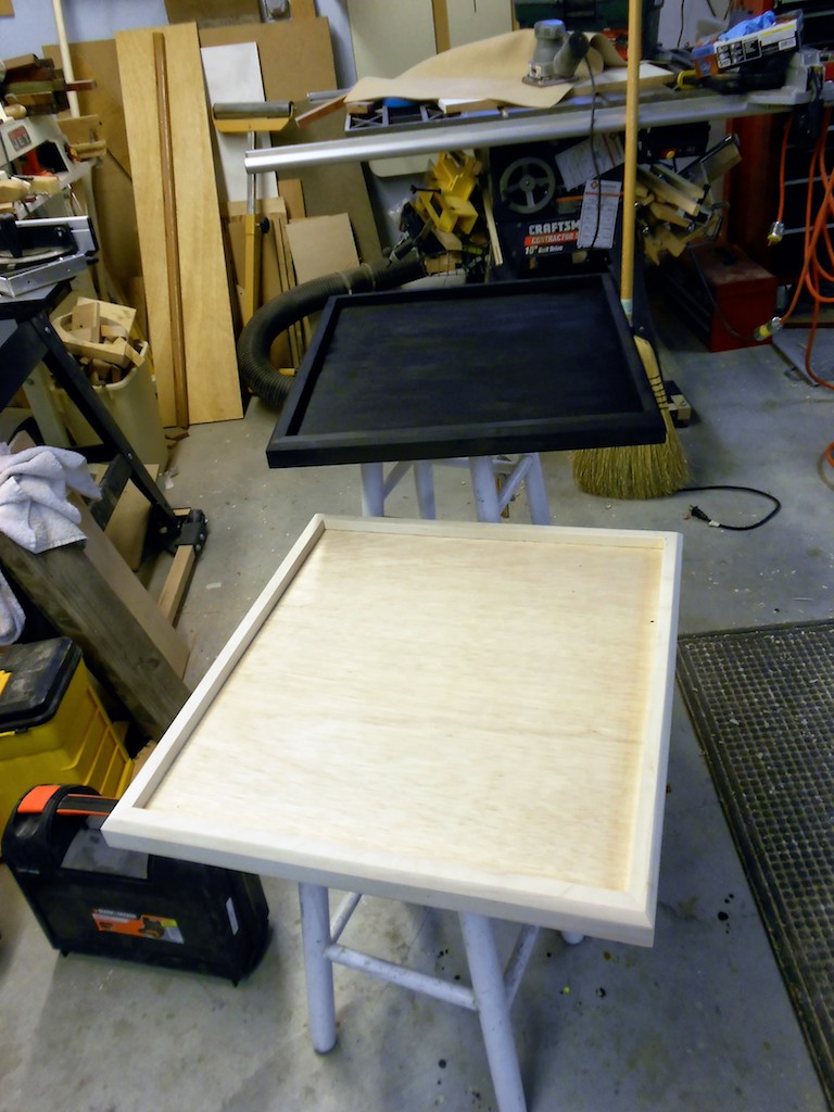
In the foreground below is the unfinished maple frame mounted on the plywood base, with the stained (but without the final finish steps) maple frame on the plywood base in the background.
While Dave was completing the finish work on the maple bases, I installed the walnut binding post blocks onto the walnut top plates, and then got busy mounting the Duelund CAST components.
Since the layout was optimized on the breadboards, all I really had to do was transfer over the Duelund CAST components to the walnut top plates.
To mount the Duelund CAST components to the walnut top plates, Pete recommended that we use straight tongue copper set screw lugs, 14-8 AWG, #10 stud, from McMaster-Carr, part number 6923K61 (I ended up using 21 of them in each crossover to complete all the wire-on-wire connections, for a total of 42, at $1.83/each USD).
The wire leads from the Duelund CAST components were inserted directly into the setscrew lugs and clamped together to give the best possible connection.
For the wiring within the crossover itself, Mark Coles recommended that I use 20 gauge Neotech solid-core UP-OCC silver wire with a Teflon jacket for the high-frequency section of the crossover (I used approximately 12 feet – 6 feet per crossover – at $21.34 USD per foot), and 14 gauge Neotech solid-core UP-OCC copper wire with a Teflon jacket for the low-frequency section of the crossover (I used slightly less than 16 feet – 8 feet per crossover – at $5.95 USD per foot).
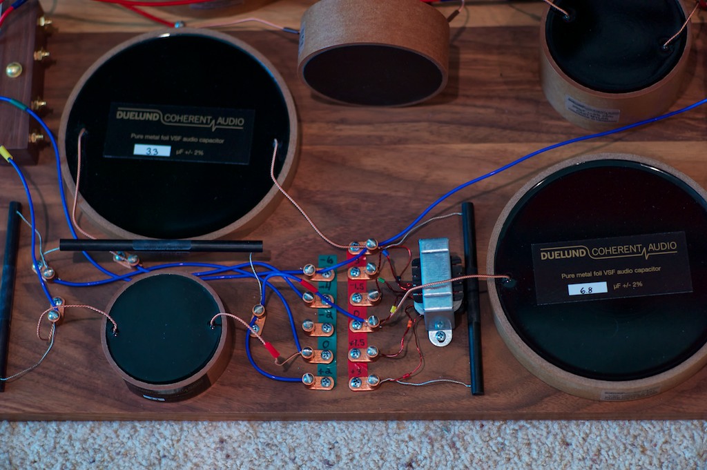
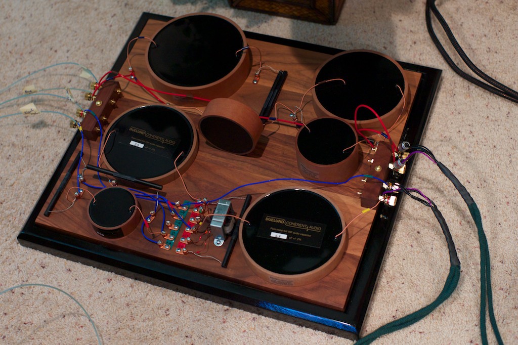
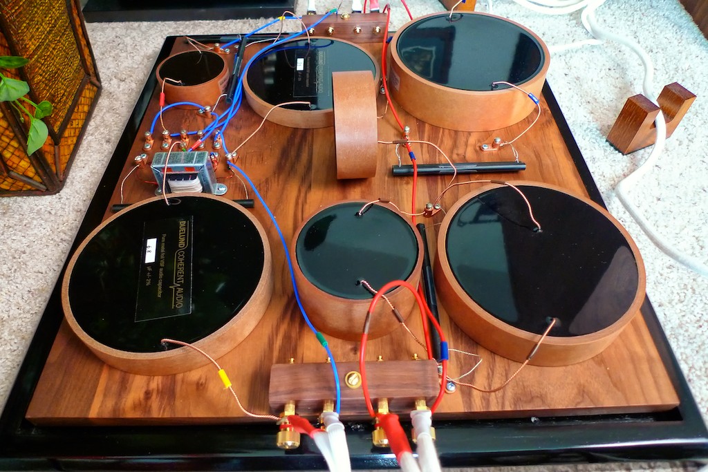
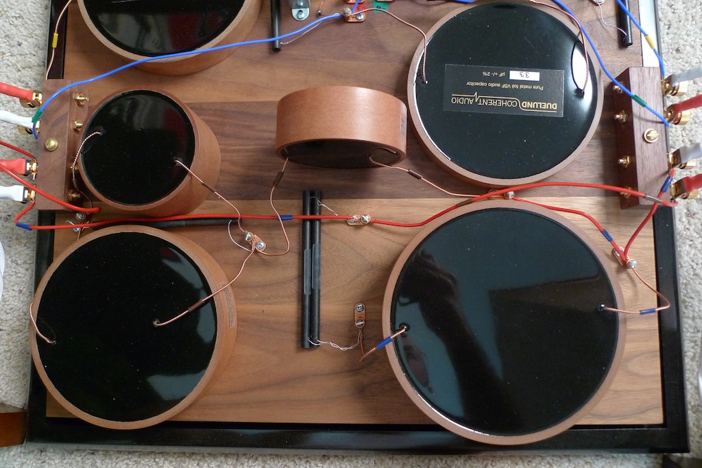
You can see the blue Neotech silver wire used in the adjustable high-frequency portion of the Duelund CAST crossover (above), and the red Neotech copper wire used in the low-frequency crossover in the photo below, now with all of the Duelund CAST components installed on the walnut top plate.

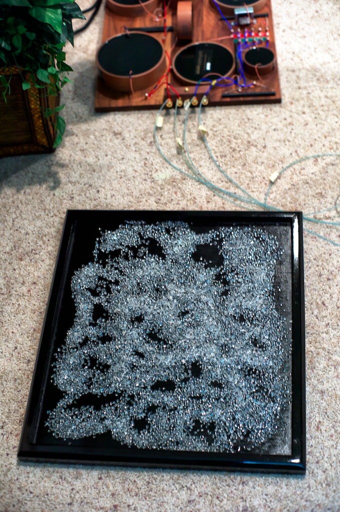
When I got the finished frames from Dave I placed the quartz granules in the bases and placed the walnut top plates into the bases, and voilà – the Duelund-Westminster CAST external crossovers were born!
A breaking news note about isolation platforms: While it will be too late coming for inclusion as part of this article, the nice people at Soundcoat Company, who have been providing specialized noise control solutions to aerospace, medical, and industrial applications since 1963, have been working with me to integrate cutting edge vibration-control technologies into the Duelund-WRSE Project isolation stands in a number of clever and easily applied ways, both by providing vibration reduction technologies for the entire stand, as well as for each of the Duelund components mounted upon them. Additionally, the Soundcoat Company will provide additional vibration control technologies that can be applied to individual components like turntables, phono equalizers, USB DACs, preamplifiers, amplifiers, and other audio applications. I will follow up in a future article to let you know the outcomes of this collaboration with Soundcoat Company on applying their vibration control technologies to audio applications. It’s an exciting topic!
A Walk-Through of the Duelund High-Frequency Crossover
Let’s take a ‘walk-through’ of the final Duelund-WRSE CAST crossover, starting with the high-frequency section, so you can see in detail how everything goes together in the final design.
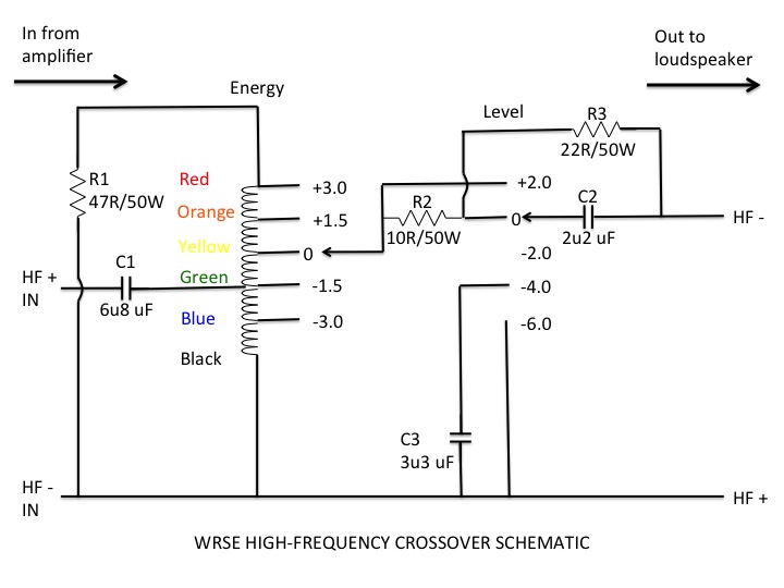
Below is my high-frequency crossover schematic for a refresher before we start our journey, so hopefully it will help make the photos and discussion a little easier to follow. I’ll start at the left side of the schematic where the signal comes in from the amplifier, and then walk my way across towards the right, where the signal goes out to the loudspeaker.
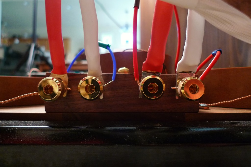
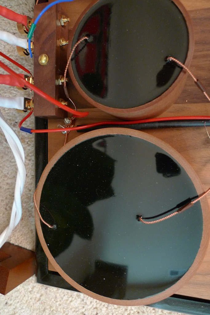
In the photo below you can see the Sablon Audio Panatela speaker cables coming in from the amplifier attached to the HF+ IN (red) and the HF- IN (white) binding posts of the Duelund CAST high-frequency crossover. (The pair of binding posts on the right side go to the Duelund CAST low-frequency crossover, which I’ll describe in a moment.)
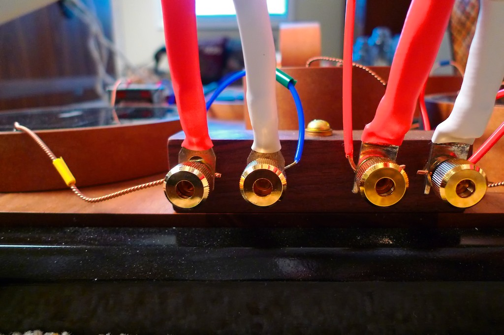
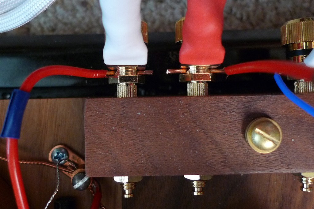
If you look closely at the photo below you can see the details of how the binding post bypass method works for connecting the Panatela speaker cables to the Duelund CAST crossover’s internal wiring: The lead from the Duelund 6.8 uF CAST capacitor (C1) inserts into the left binding post’s wire passage. The silver spade connector from the positive (red) Panatela cable coming in from the amplifier slips over the binding post shaft directly in front of the wire lead from the Duelund capacitor. When the binding post cap nut is tightened down it clamps the Panatela’s spade and the Duelund CAST capacitor lead wire tightly together to make the electrical connection, thus avoiding a signal degrading solder connection, and making for the most direct connection of the speaker cables spade connector possible to the crossover’s internal wiring.
On the right binding post a 20-gauge Neotech silver wire (blue) is inserted into the right binding post’s wire passage. The silver spade connector from the negative (white) Panatela speaker cable coming in from the amplifier slips over the binding post shaft directly in front of the Neotech silver wire lead, and when the binding post cap nut is tightened down it clamps the Panatela’s spade and the Neotech silver wire tightly together. As passing the signal through binding posts as part of a circuit degrades the signal somewhat, the binding post bypass method is a truly nice way to get the binding posts out of the circuit and at the same time avoiding an equally signal degrading solder connection!
Thanks again to Mark Coles for the idea of using the binding post bypass method of connecting speaker cables to the crossover’s internal wiring, it’s truly an elegant way to preserve the fidelity of the audio signal passing through the circuit as much as possible.
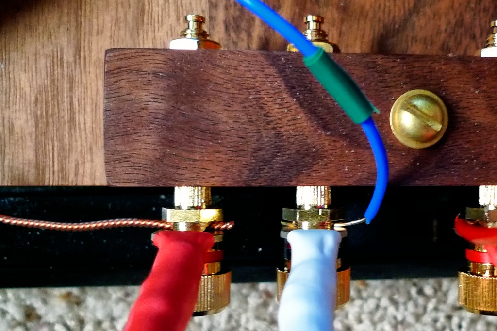
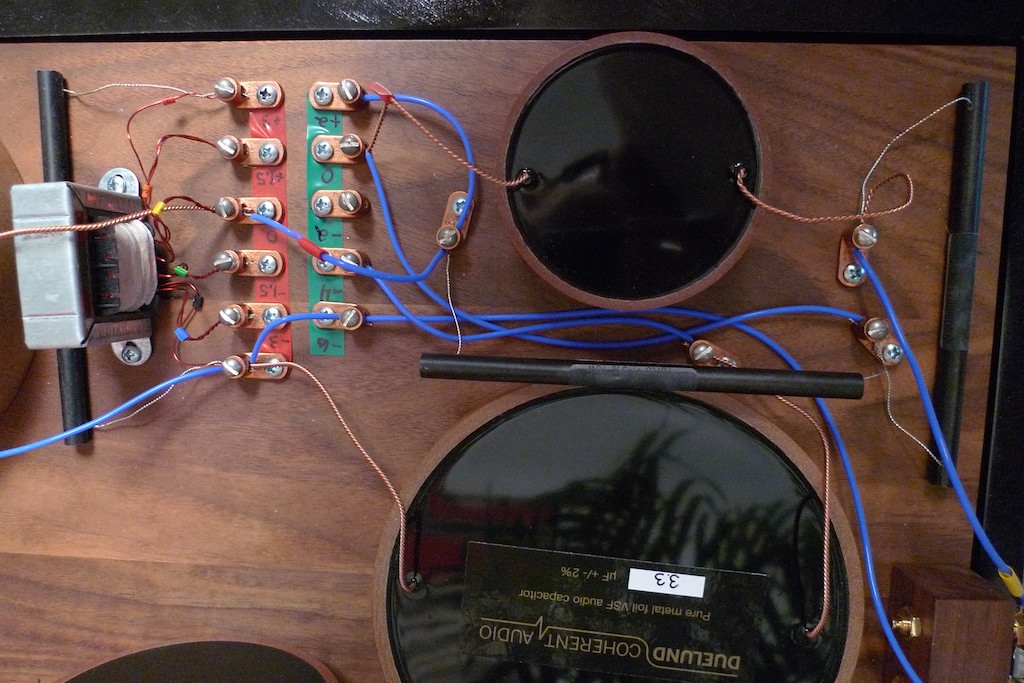
In the photo below you can see the entry lead (with the yellow tape marker) going from the HF+ IN binding post into the C1 Duelund 6.8 uF CAST capacitor, and from the HF- IN binding post you can see the 20-gauge Neotech silver wire (blue wire with green tape marker) going off into the distance to connect at the setscrew lug that connects to the black wire on the autotransformer, the R1 Duelund 47R/5W Carbon/Silver CAST resistor, and the C3 Duelund 3.3 uF CAST capacitor.
The copper setscrew lugs serve the same sort of clamping function as the binding posts do in the binding post bypass method, where the setscrew simply clamps the two wires tightly together in the lug for a signal-preserving solder-free connection. To maintain as much signal fidelity as possible, there are absolutely no solder joints used in the Duelund CAST external crossovers. Only the leads from the Duelund CAST components, connected where necessary with the shortest possible lengths of the ultra-quality Neotech hookup wire, make up all the wiring used in the circuits, and all connections are made with the setscrew lugs.
Thanks to Pete Riggle for suggesting the idea of using the copper setscrew lugs to connect the Duelund components’ leads to the crossovers’ internal Neotech wiring, as it’s truly a superb way to preserve the fidelity of the audio signal passing through the circuit as much as possible, with the added bonus of being able to quickly change out a component should that be desired.
In the photo above you can see the lead from the Duelund 6.8 uF CAST capacitor (C1) inserting into the red-tape side -1.5 dB treble energy level setscrew lug where it connects to the green lead of the autotransformer (the 3rd red-side setscrew lug up from the bottom of the photo).
The photo above also shows a close-up of the aforementioned 20-gauge Neotech silver wire (blue) coming in from the negative binding post and inserting into the bottom red-tape side setscrew lug that connects the black wire on the autotransformer, the R1 Duelund 47R/5W Carbon/Silver CAST resistor, and the C3 Duelund 3.3 uF CAST capacitor.
You can see the R1 Duelund 47R/5W Carbon/Silver CAST resistor positioned between the C1 Duelund 6.8 uF CAST capacitor and the autotransformer. Note that R1 Duelund 47R/5W Carbon/Silver CAST resistor also inserts into the red-side +3 dB treble energy level setscrew lug (the top setscrew lug on the red-tape side in the photo below).
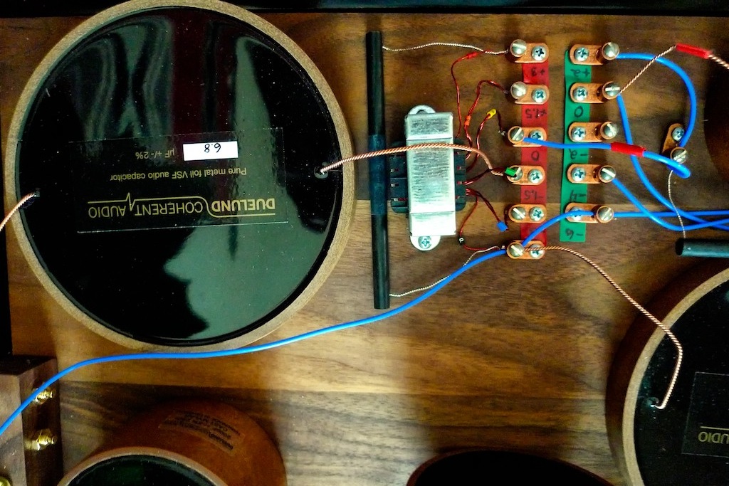
As with the stock internal Tannoy WRSE crossover, the Duelund CAST external crossover allows the treble energy level of the tweeter to be adjusted over a range of -3 dB to +3 dB by selecting different taps on the autotransformer that increase or decrease the tweeter energy level in 1.5 dB steps from the crossover point.
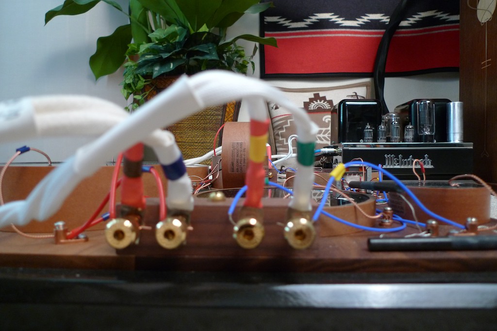
In the Duelund CAST crossover this is accomplished by moving a jumper wire in the crossover to connect to the appropriate autotransformer tap (from top to bottom in the photo below: the red tap is +3 dB, the orange tap is +1.5 dB, the yellow tap is +0 dB, the green tap -1.5 dB, and the blue tap -3 dB).
In the photo below you can see a length of 20-gauge Neotech silver wire (blue with a red tape marker) that is inserted into the +0 dB treble energy level setscrew lug (on the ‘red-side’) that connects it to the yellow tap (+0 dB) from the autotransformer. This is the jumper wire that can be moved between the different red-side setscrew lugs corresponding to the autotransformer taps that adjust the treble energy level of the tweeter. In the photo, the Neotech jumper wire is inserted into the +0 dB treble energy level setscrew lug, which means that there is zero alteration of tweeter’s treble energy level.
As we move to the right in the photo (and schematic), the other end of Neotech movable jumper wire is connected to the R2 Duelund 10R/10W Carbon/Silver CAST resistor (which is the horizontal resistor in the middle of the photo) via a setscrew lug that you can see just to the left of the C2 2.2 uF Duelund CAST capacitor (the capacitor in the upper right of the photo). A length of Neotech silver wire also goes from this setscrew lug to the +2 dB treble roll-off control that is at the top of the green tape strip in the photo.
A length of 20-gauge Neotech silver wire (blue) goes from the -3 dB treble energy level setscrew lug (red side) to the -6 dB treble roll-off level setscrew lug (green side), and then all the way to the HF+ OUT binding post that goes out to the loudspeaker, where it is clamped to the silver spade of the positive lead (red) of the internal WRSE Panatela wire (lower right-hand corner of the photo).
The treble roll-off circuitry functions as a variable low pass filter, which I’ll explain in more detail in a moment, but first let me describe what it does visually by using the diagrams from the front panel of the WRSE treble controls, which I think will give you more of an intuitive feel for what the circuitry does.
If you look at the photo below, the diagram underneath the treble energy level control (the left control) shows that when the different transformer taps are selected the treble energy level is changed in steps over the range of +3 dB to -3 dB at the crossover point, but the change in dB is linear in response with increasing frequency from the crossover point.
In the diagram underneath the treble roll-off level control, you can see that the change in dB response is non-linear with increasing frequency. The treble roll-off control provides an increasingly greater dB change in treble response as a function of increasing frequency in a smooth curve (i.e. dB response ‘rolls-off’ with increasing frequency).
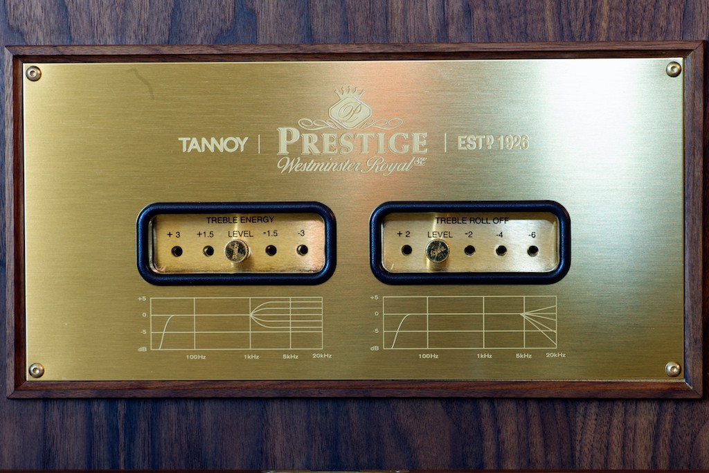
In discussing the treble roll-off control with Paul Mills, he told me that its inclusion in the WRSE’s circuit is largely historical in nature, as its original purpose was to tailor the high-frequency response to help reduce the hiss on 78 rpm records. Paul told me that he had considered removing the treble roll-off control from the circuit as it doesn’t really serve a useful purpose for modern recordings, but a very enthusiastic core group of Westminster owners who still listen to 78s wanted him to retain it, so he did. Paul advises those not listening to 78s on their Westminsters to ignore the treble roll-off control!
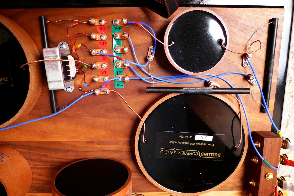
Ok, now let’s continue our walk across the high-frequency crossover. Take a look at the row of setscrew lugs on the green tape in the photo below – these are the treble roll-off level controls for the Duelund CAST crossover. If you have a lot of 78s to listen to you might want to change the treble roll off setting from the normal +0 dB setting to +2 dB, -2 dB, -4 dB, or -6 dB to best flatter your particular 78 rpm record.
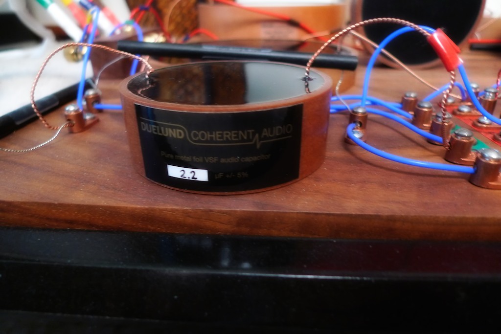
To change the treble roll-off to best complement the 78 rpm record you want to listen to, you would move the lead of the C2 2.2 uF Duelund CAST capacitor (marked with the red tape in the photo) to the setscrew lug with the desired level of roll-off. (It’s the capacitor in upper right of the photo above, with a close-up below.)
+2 dB setting: If you insert the C2 2.2 uF Duelund CAST capacitor lead into the +2 dB setscrew lug, it places the R2 Duelund 10R/10W Carbon/Silver CAST resistor and the R3 Duelund 22R/10W Carbon/Silver CAST resistor in parallel with the C2 2.2 uF Duelund CAST capacitor to give +2 dB of roll-off on its way to HF- OUT.
+0 dB setting: If you insert the C2 2.2 uF Duelund CAST capacitor lead into the +0 dB setscrew lug, it places the R2 Duelund 10R/10W Carbon/Silver CAST resistor in series with the C2 2.2 uF Duelund CAST capacitor, and the R3 Duelund 22R/10W Carbon/Silver CAST resistor in parallel with the C2 2.2 uF Duelund CAST capacitor, to give 0 dB of roll-off on its way to HF- OUT.
Note: In my original posting I made a mistake in describing how the circuit works to achieve the +2dB and +0dB settings. The text has now been corrected. A big 'Thank you!' to the very astute Carlos Margutti for pointing this out - very much appreciated!
-2 dB setting: If you insert the C2 2.2 uF Duelund CAST capacitor lead into the -2 dB setscrew lug, it drops the C2 2.2 uF Duelund CAST capacitor out of the circuit, and the HF+ IN signal from the transformer tap goes through the R2 Duelund 10R/10W Carbon/Silver CAST resistor and the R3 Duelund 22R/10W Carbon/Silver CAST resistor, to give -2 dB of roll-off on its way to HF- OUT.
-4 dB setting: If you insert the C2 2.2 uF Duelund CAST capacitor lead into the -4 dB setscrew lug, the HF+ IN signal from the transformer tap goes through the R2 Duelund 10R/10W Carbon/Silver CAST resistor and the R3 Duelund 22R/10W Carbon/Silver CAST resistor on its way to HF- OUT, and it places the C2 2.2 uF Duelund CAST capacitor and the C3 3.3 uF Duelund CAST capacitor in series across the driver terminals to act as a low pass filter, to give -4 dB of roll-off.
-6 dB setting: If you insert the C2 2.2 uF Duelund CAST capacitor lead into the -6 dB setscrew lug, the HF+ IN signal from the transformer tap goes through the R2 Duelund 10R/10W Carbon/Silver CAST resistor and the R3 Duelund 22R/10W Carbon/Silver CAST resistor on its way to HF- OUT, and it places the C2 2.2 uF Duelund CAST capacitor across the driver terminals to act as a low pass filter, to give -6 dB of roll-off.
Once the incoming signal goes through the treble roll-off level control it ends up at the HF-/HF+ OUT pair of binding posts, which connects to the Panatela internal cabling from the Westminsters using the binding post bypass technique as described earlier (below).
Ok, that’s it for the high-frequency section of the Duelund CAST external crossover, so now lets walk through the low-frequency section.
A Walk-Through of the Duelund Low-Frequency Crossover
The adjustability of the high-frequency crossover makes it more difficult to understand what is occurring in the circuit as different energy & level settings are selected, but fortunately the low-frequency crossover’s fixed design makes it relatively easy to follow.
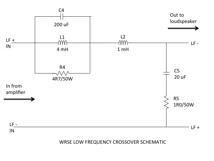
For a refresher, above is the schematic for the low-frequency crossover. We’ll start at the left side of the schematic where the signal comes in from the amplifier and work our way across towards the right.
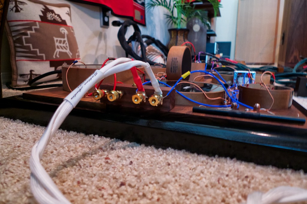
In the photo below you can see the pair of LF+/LF- IN binding posts on the right that the Panatela speaker cables coming from the amplifier attach to.
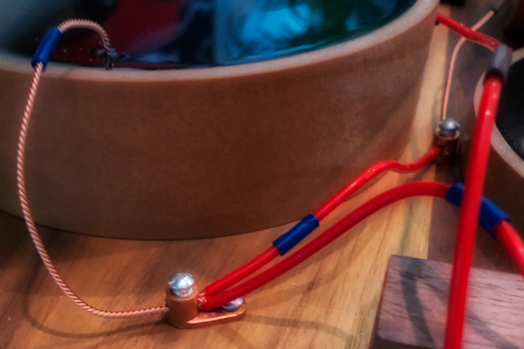
As with the high-frequency binding posts, the low-frequency binding posts also use the bypass method (below) to clamp the 14-gauge Neotech solid-core UP-OCC copper wire (red) used for wiring in the low-frequency crossover to the Panatela speaker cables silver spade connectors.
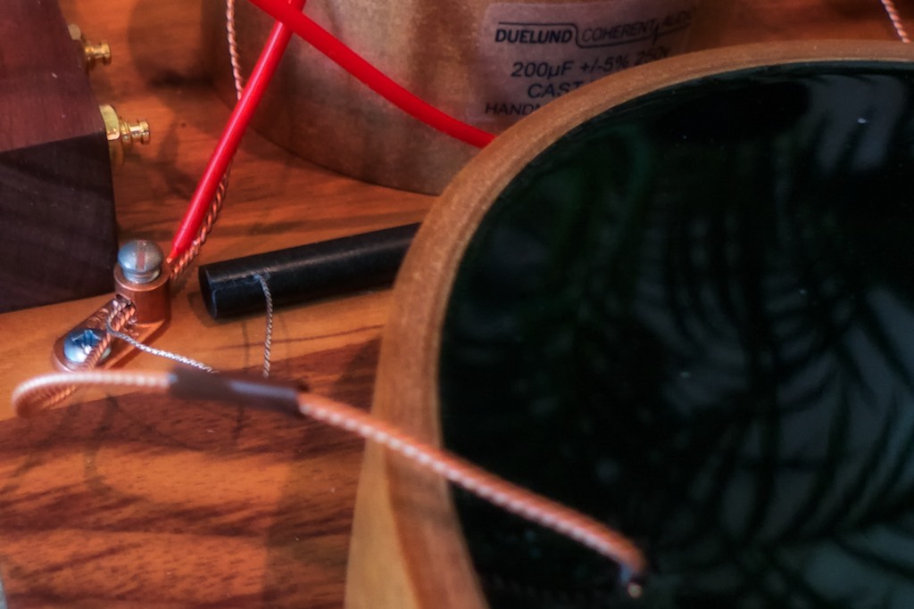
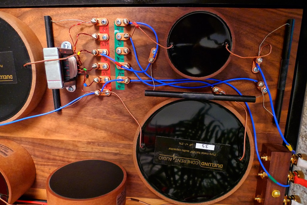
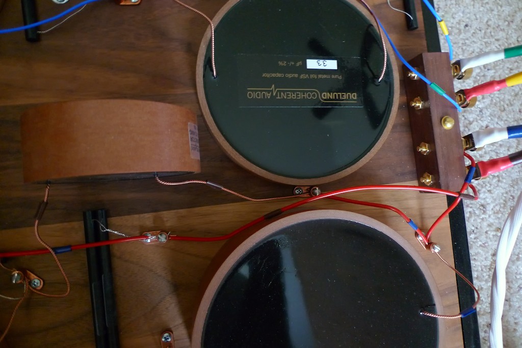
In the photo below a length of 14-gauge Neotech copper wire goes from the LF+ binding post to a setscrew lug that connects the leads in parallel from the C4 Duelund 200 uF Mylar CAST capacitor (at the top in the photo), the R4 Duelund 4R7/10W Carbon/Silver CAST resistor (between the capacitor & inductor), and the L1 Duelund 4 mH PIO Copper Air Core CAST inductor (at the bottom in the photo).
Below is a close-up photo of the setscrew lug that connects the length of 14-gauge Neotech copper wire from the LF+ binding post to the leads from C4, R4, and L1 in parallel.

In the photo below you can see that on the right side of C4, R4, and L1 there is a setscrew lug that connects their leads in parallel, while adding in the lead for the L2 Duelund 1 mH PIO Copper Air Core CAST inductor, which is visible in the upper right corner of the photograph.
The L2 Duelund 1 mH PIO Copper Air Core CAST inductor is positioned perpendicular to the L1 Duelund 4 mH PIO Copper Air Core CAST inductor so their magnetic fields don’t interfere with each other.
In the photo above you can also see the two Duelund 2R0/10W Carbon/Silver CAST resistors that are paralleled to give a 1R0 value in the R5 position of the circuit.
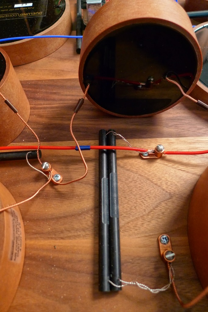
In the photo below you can see the leads of the paralleled 2R0 Duelund resistors nearest the L2 Duelund 1 mH PIO Copper Air Core CAST inductor connect at a setscrew lug that intersects a length of 14-gauge Neotech copper wire that goes all the way from the LF- IN binding post to the LF+ OUT binding post.
In the photo above you can see that the leads of the paralleled 2R0 Duelund CAST resistors furthest from the L2 Duelund 1 mH PIO Copper Air Core CAST inductor connect at a setscrew lug to the lead from the C5 20 uF Duelund CAST capacitor.
The other lead from the C5 20 uF Duelund CAST capacitor connects to the L2 Duelund 1 mH PIO Copper Air Core CAST inductor at the setscrew lug on the far right of the crossover, and a short length of 14-gauge Neotech copper wire connects it to the LF- OUT binding post (see close-up below).
The LF+/LF- OUT to the Westminster connects the 14-gauge Neotech copper wiring of the low-frequency crossover to the Panatela internal wiring using the binding post bypass method, as with the high-frequency crossover (below).
Now that we’ve completed our ‘walk-throughs’ of the final versions of the Duelund-WRSE external crossovers, let’s get started on the next major project phase, rewiring the Westminster Royals SEs with Sablon Audio Panatela speaker cables so they can get the best from the Duelund CAST external crossovers!
Ok friends, that's it for now. Next up will be Part 4 covering the rewiring of the Westminster Royal SEs to get the most out of the Duelund-WRSE external crossovers.
Thanks for stopping by!