The full Duelund-Westminster External Crossover Project article has been submitted to the Ye Olde Editors Dave and David of Positive Feedback Online for publication in the November 2013 issue next week. The article is 41 pages long and includes 137 photographs - it is a doozy!
As I mentioned in my Part 1 sneak peak, here is another sneak peak for you to enjoy until the full article is published next week.
Continued from Part 1:
Designing the Duelund-Westminster External Crossovers
Caution: If you choose to try and duplicate what I did in the Duelund-WRSE Project with your own loudspeakers, you do so at your own risk, and you are solely responsible for any damage or harm you inflict upon yourself, your loudspeakers, or your domestic relationships. If you burn your house down inadvertently while doing the project, that one’s on you too. 🙂
Ok, now that I’ve discussed the three types of Duelund CAST components that will go into the Duelund-Westminster project crossovers (capacitors, inductors, and resistors), let’s talk about the crossovers’ layout so we can see what goes where.
The first thing I did was to sketch out the circuit diagrams for both the high- and low-frequency crossovers, and then I figured out which Duelund CAST component parts I would need (and how many) so I could let Frederik know so he could get started making them.
My circuit diagram for the WRSE high-frequency (HF) crossover is below:
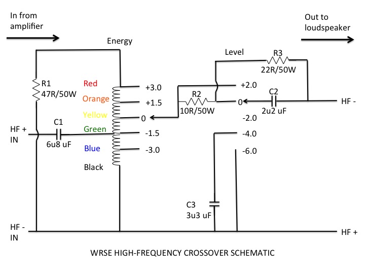
For orientation, in the schematic above the signal comes into the HF crossover from the amplifier on the left, and goes out of the HF crossover to the loudspeaker on the right. The list of components needed for one HF crossover are shown below (you’ll need to double the amount to build the two HF crossovers you’ll need for both your speakers):
- R1 is a 47R/50W resistor.
- R2 is a 10R/50W resistor.
- R3 is a 22R/50W resistor.
- C1 is a 6u8 uF capacitor.
- C2 is a 2u2 uF capacitor.
- C3 is a 3u3 uF capacitor
Under the ‘Energy’ portion of the schematic is the autotransformer that is used for the treble energy level control. According to Dr. Paul Mills (Director of Research & Engineering at Tannoy), the autotransformer is a very important part of the circuit and cannot be omitted even if you don’t plan on using the adjustability it brings to the high frequencies. Under the ‘Level’ portion of the schematic are the treble roll-off controls, which I’ll discuss in detail a little later in the article.
For your own Duelund-WRSE Project, you’ll probably just want to use the well broken in pair of autotransformers off your original crossover boards, but if not, then you can order a new pair through your local Tannoy dealer. If you don’t have a local Tannoy dealer then you can go to the Tannoy Sales & Service page of the Tannoy website and you should be able to track down someone who can get them for you.
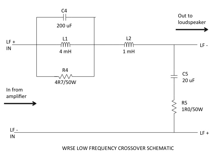
Now lets discuss the low-frequency (LF) crossover: For orientation, in the schematic above, the signal comes into the LF crossover from the amplifier on the left, and goes out of the LF crossover to the loudspeaker on the right. The list of components needed for one LF crossover are shown below (you’ll need to double the amount to build the two LF crossovers you’ll need for both your WRSE speakers):
- R4 is a 4R7/50W resistor.
- R5 is a 1R0/50W resistor.
- C4 is a 200 uF capacitor.
- C5 is a 20 uF capacitor.
- L1 is a 4 mH inductor.
- L2 is a 1 mH inductor.
A couple of notes about resistors: The stock Tannoy WRSE crossovers use 50W rated resistors (as above), so you might be wondering if it is safe to use the Duelund CAST resistors that are rated at 5 or 10W depending on the resistor. I had the same question so I consulted with Dr. Paul Mills at Tannoy, and he told me the 5 W or 10W Duelund CAST resistors would be fine in all positions, saying “The 50W resistors require a very large heat sink for that rating, and with no heat sink will de-rate to around 10W or less.” I have been using the 5W & 10W Duelund CAST Carbon/Silver resistors in my crossovers for some time now, and they have functioned flawlessly, with no signs of being thermally stressed.
Also, you should note that the R5 position 1R0/10W resistors in the schematic are not a standard Duelund CAST resistor value, so you’ll need to use a pair of 2R0/10W Duelund CAST resistors in parallel to achieve the 1R0/10W value in the R5 position of each LF crossover.
Once I had worked up the full list of components from the schematics, I was able to let Frederik know the full Duelund CAST components count needed for the Duelund-Westminster crossovers so he could start building them (the prices I have included below are the discounted prices listed at Parts Connexion as of September 2013):
|
Schematic Position |
Duelund CAST Component |
Price (USD) |
Number Required |
Total |
|
High Frequency Crossover |
||||
| R1: 47R/50W resistors | 47R/5W Carbon/Silver resistors |
$52.06/each |
2 |
$104.12 |
| R2: 10R/50W resistors | 10R/10W Carbon/Silver resistors |
$52.06/each |
2 |
$104.12 |
| R3: 22R/50W resistors | 22R/10W Carbon/Silver resistors |
$52.06/each |
2 |
$104.12 |
| C1: 6u8 uF capacitors | 6.8uf/100VDC PIO Copper Foil capacitors |
$666.41/each |
2 |
$1332.82 |
| C2: 2u2 uF capacitors | 2.2uf/100VDC PIO Copper Foil capacitors |
$422.30/each |
2 |
$844.60 |
| C3: 3u3 uF capacitors | 3.3uf/100VDC PIO Copper Foil capacitors |
$484.10/each |
2 |
$968.20 |
|
Low Frequency Crossover |
||||
| R4: 4R7/50W resistors | 4R7/10W Carbon/Silver resistors |
$52.06/each |
2 |
$104.12 |
| R5: 1R0/50W resistors | 2R0/10W Carbon/Silver resistors |
$52.06/each |
4 |
$208.24 |
| C4: 200 uF capacitors | 200 uF/100VDC Mylar CAST capacitors |
$510.53/each |
2 |
$1021.06 |
| C5: 20 uF capacitor | 20uf/100VDC PIO Copper Foil capacitors |
$1905.50/each |
2 |
$3811.00 |
| L1: 4 mH inductors | 4 mH PIO Copper Air Core inductors |
$1225.70/each |
2 |
$2451.40 |
| L2: 1 mH inductors | 1 mH PIO Copper Air Core inductors |
$674.13/each |
2 |
$1348.26 |
|
|
Total Price |
$12,402.18 |
||
As Frederik alluded to, the Duelund CAST components can take quite a while to build, particularly for this size of an order, and depending on how many orders are in the queue at the time you place your order, you should be prepared to be patient, but don’t fret, your patience will be rewarded. After I provided Frederik the list of the Duelund CAST components I would need for the WRSE crossovers - towards the end of December - I settled in for the wait for them to arrive.
Summary Scope for the Duelund-WRSE Project
While I was waiting for the Duelund components to arrive, I put the time to good use, and had discussions with Frederik Carøe (Duelund Coherent Audio), Mark Coles (Sablon Audio), Paul Mills (Tannoy), David Biancosino (Dave Biancosino, Answers in Art), Pete Riggle (Pete Riggle Audio Engineering), and Pambos on how best to implement the Duelund crossovers, to address the internal wiring of the WRSEs, and to pick the best options for other details related to the Duelund-WRSE crossover project.
First let me summarize the scope of the Duelund-WRSE Project that we came up with, and then I’ll elaborate more as I describe each step of the project as I go along so you can follow along in detail.
Essentially the project scope consists of two major pieces: building the Duelund external crossovers, and rewiring and modifying the internals of the Westminster Royal SE loudspeakers.
- Building the Duelund external crossovers:
- Build the Duelund external crossovers onto vibrational energy dissipation platforms similar in concept to the Acoustic Revive RST-38 Under-Boards (one of my favorite audio stands), to provide additional isolation from floor borne vibration.
- Use the binding-post-bypass method to attach the Panatela internal cabling & Panatela speaker cables to the Duelund external crossover.
- Use straight tongue copper setscrew lugs from McMaster-Carr for mechanical connections of wires on the crossover boards.
- Use 20 gauge Neotech solid-core UP-OCC silver wire with a Teflon jacket for the high-frequency section of the crossover.
- Use 14 gauge Neotech solid-core UP-OCC copper wire with a Teflon jacket for the low-frequency section of the crossover.
- Internal modifications to the Westminster Royal SE loudspeakers:
- Remove the WRSEs’ stock internal wiring connectors, driver connecting plugs, and binding posts.
- Use one continuous run of Panatela internal cabling from the Dual Concentric™ drivers to the Duelund external crossovers.
- Connect the Panatela LF cables directly to the Dual Concentric™ low frequency drivers’ leads with WTB crimp sleeves.
- Solder the Panatela HF cables directly to the Dual Concentric™ High frequency drivers’ connections with WTB leaded silver solder.
- Solder the Panatela ground cables directly to the Dual Concentric™ driver grounds with WTB leaded silver solder.
Keeping the high-level project scope in mind, let’s proceed with executing the steps of the project. I’ll do my best to describe every step of the project in enough detail so that you can figure out how to duplicate the steps for your own project.
The Duelund Components Arrive!
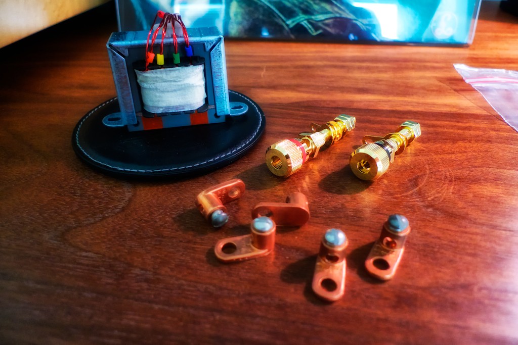
I received the shipment of Duelund CAST components around the middle of April after letting Frederik know what was needed for the project in December timeframe, although the development of the 200 uF CAST Mylar capacitors did add to the time needed to pull together the full set of components needed.
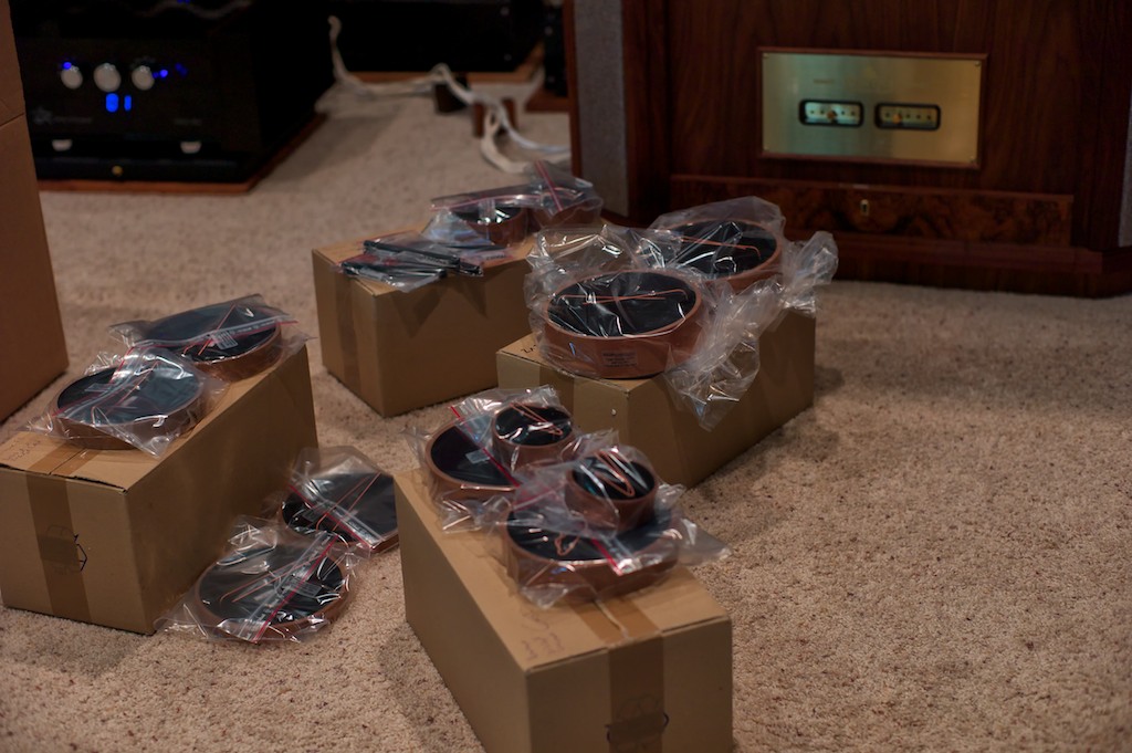
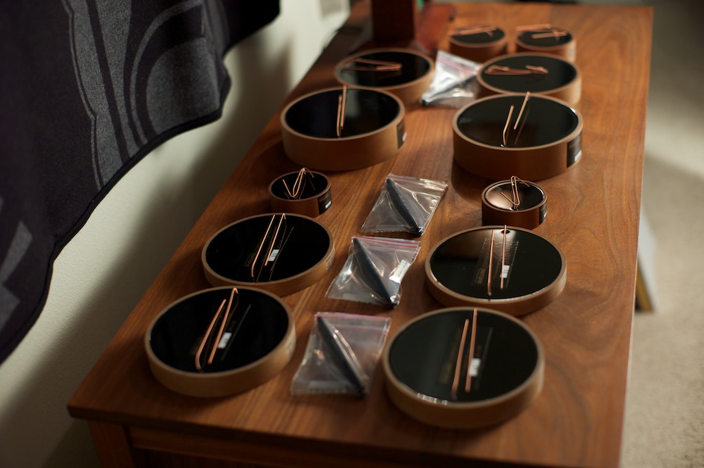
I was stunned when the boxes of Duelund CAST components for the WRSE crossovers arrived (above). I had never seen the Duelund CAST components in person before, and it was quite a sensual treat unpacking them from their shipping containers, holding them in my hands and feeling their substantial mass & size, and if I may say so, admiring the beautiful quality of their construction and their impeccable finish.
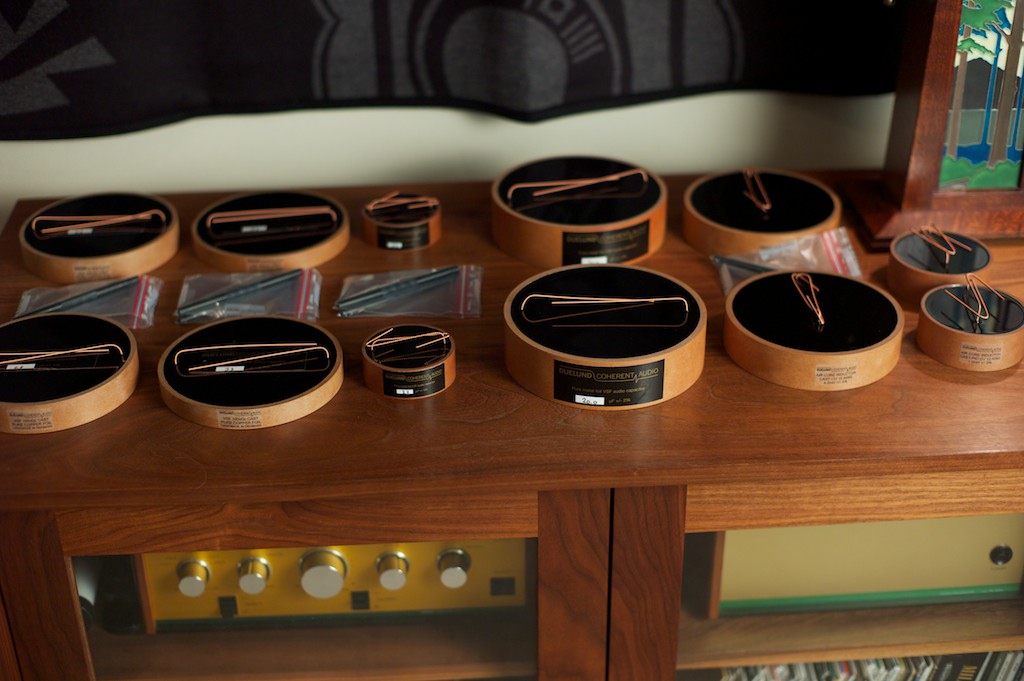
I laid the Duelund CAST components all out on my cabinet – except for 200uF Duelund CAST Mylar capacitors that hadn’t arrived yet – for a photo shoot. As a number of my Jeff’s Place blog readers and friends have noted, the Duelund CAST components are artistic & attractive in their own right, something that you don’t expect from capacitors, inductors, and resistors, and I really wanted to the external crossovers to visibly show their artful aspects to visitors to my listening room – they really are something to behold.
Breadboarding the Duelund External Crossovers
The breadboarding of the Duelund external crossovers proceeded according to the following steps:
- Build a left-channel high & low-frequency crossover breadboard using color-coded Elenco alligator clip leads to help visualize how the Duelund components could be positioned and wired together.
- Rewire the left-channel high & low-frequency crossover breadboard using generic hookup wire and wire nuts, then test the crossover on the WRSE to make sure the circuit worked as expected.
- Build a right-channel high & low-frequency crossover breadboard using generic hookup wire and wire nuts with further optimization of the placement of the Duelund components.
- Test the left & right-channel crossovers on the Westminster Royal SEs to make sure the circuits worked correctly.
Well you can only do so much planning, and now having most of the parts in hand, it was time to layout the Duelund external crossovers. The first step was to blow up the crossover schematics to actual ‘Duelund-size’ to better visualize how to lay out the components, which was the easy way to see how the components for the circuits might best fit together on the breadboards.
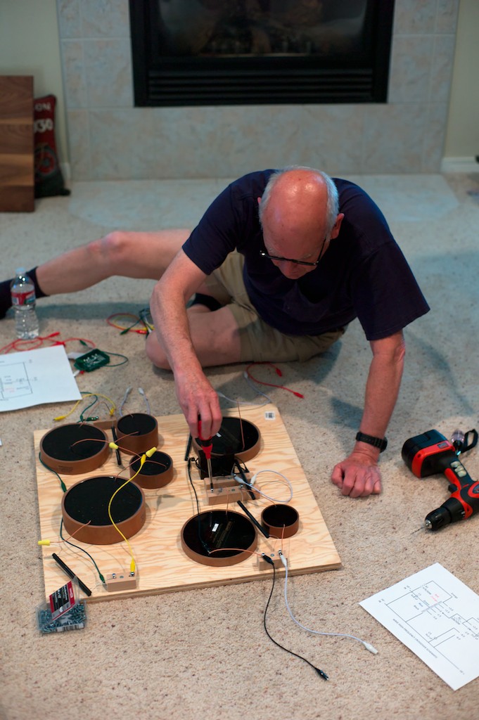
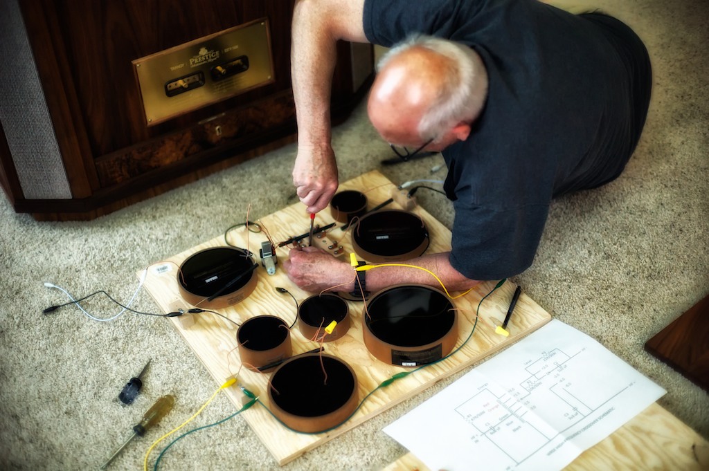
Audio pals Pete Riggle and Stephaen Harrell, who have done a number of external crossover projects for their own loudspeakers, came by to help me breadboard the left-channel Duelund-WRSE high & low-frequency crossover, then once I was sure I understood what was going on with the circuits, I would take it from there. Thanks to Pete & Stephaen for helping me get off to a good start!
To serve as the base for the breadboards we used 2-foot squares of plywood to give us plenty of room. At this point we were not trying to make things pretty, we just wanted to make sure we understood the circuits and how all the components went together. Here’s Pete doing some basic layout according to the schematic (below).
I decided I wanted to leave the original crossovers intact and in place in my Westminster Royal SE loudspeakers - but out of the circuit - in case I ever wanted to restore my West’s to original condition. That meant I needed a pair of Tannoy autotransformers to complete the Duelund-WRSE high-frequency crossover circuit, which Dr. Paul Mills graciously provided to use for the project. Thank you Paul!
As I mentioned earlier, if you decide you want to duplicate this project for your own Tannoys, you’ll probably just want to use the autoformers off your original crossover boards, but if not, then you can order a pair through your local Tannoy dealer. If you don’t have a local Tannoy dealer then go to the Tannoy Sales & Service page of the Tannoy website, and you should be able to track down someone who can get them for you.
Just as an aside: Pambos, Paul, and myself discussed the possible benefits of using autotransformers with silver windings and nickel cores. It is something we’d all like to try, but at this point in time getting special sets of autotransformers made up was a little bit too daunting of a challenge to do in time for the project. Perhaps in the future I’ll be able to follow up on that idea, and if so, then I’ll report back on the results.
You’ll notice that the autotransformer is missing from the parts selection in the photo above, as Paul was so busy getting everything ready for his upcoming Munich Hi-Fi show at the time, he didn’t have a chance to get a set of autotransformers shipped out yet, but we knew how big they were so we were still able to do a basic layout.
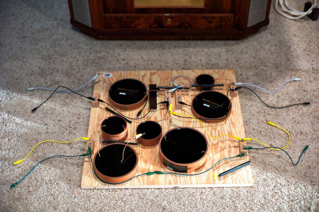
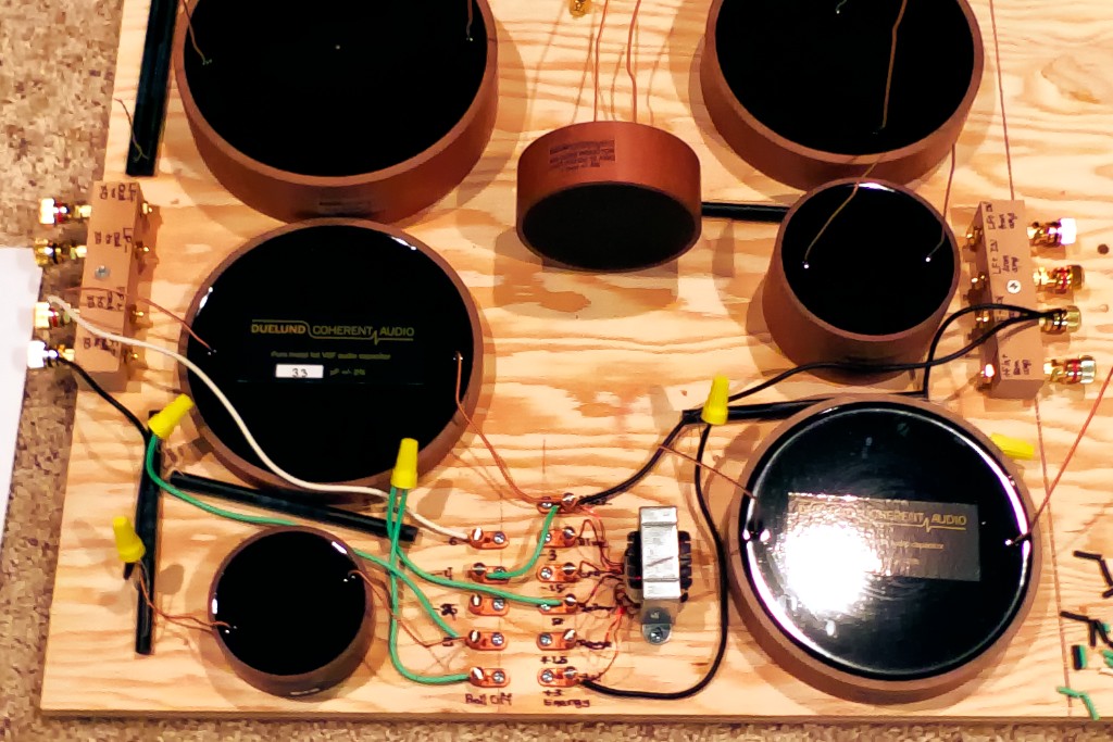
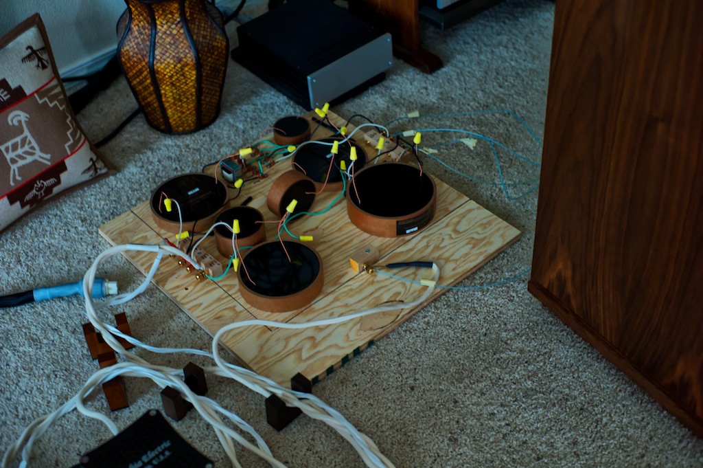
In the top half of the breadboard you can see the components laid out according to the high-frequency crossover schematic. An Acoustic Revive cable riser was pressed into service as a mock autotransformer for the purpose of laying out the breadboard until Paul’s autotransformers showed up (they’re about the same size). In the upper left of the breadboard the white Elenco alligator clip lead represents the HF+ IN from the amplifier, and the black Elenco Alligator clip lead represents the HF- IN from the amplifier. On the upper right side of the breadboard you’ll notice that white Elenco alligator clip lead represents the HF- OUT to the loudspeaker, and the black Elenco Alligator clip lead represents the HF+ OUT to the loudspeaker.
In the bottom half of the breadboard you can see the components laid out according to the low-frequency crossover schematic. On the bottom left side of the breadboard the green Elenco alligator clip lead represents the LF- IN from the amplifier, and the yellow Elenco alligator clip lead represents the LF+ IN from the amplifier. On the bottom right of the breadboard the green Elenco alligator clip lead represents the LF+ OUT to the loudspeaker, and the yellow Elenco alligator clip lead represents the LF- OUT to the loudspeaker.
The color-coded Elenco alligator clip leads were only used to help visualize how the crossovers would be wired together, and of course they were not used in the final design. I ordered a couple of sets of the Elenco TL-6 Standard Alligator 10-Piece Lead Set from Amazon.com at $5.77 each, and they turned out to be really handy for visualizing how the Duelund components were to be wired together on the crossover, and to determine what lengths of Neotech wire would be needed for the final wiring of the crossovers.
Once the Tannoy autotransformers arrived from Paul we got busy putting them in place on the breadboard (below).
At this point we also began to rewire the left-channel high & low frequency breadboard crossover using generic hookup wire and wire nuts, readying it for eventual testing on the loudspeaker to make sure the circuit was working as expected.
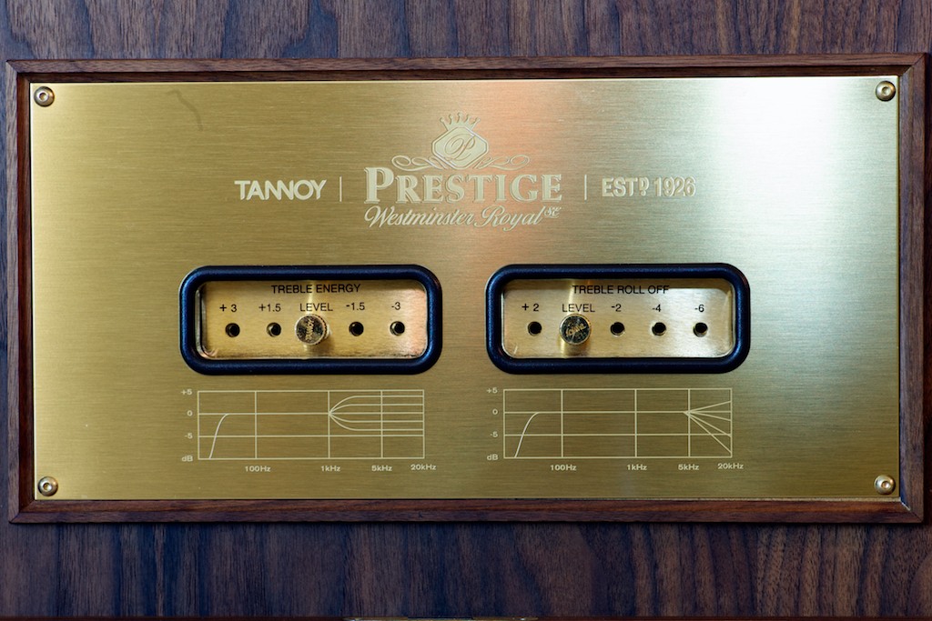
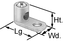
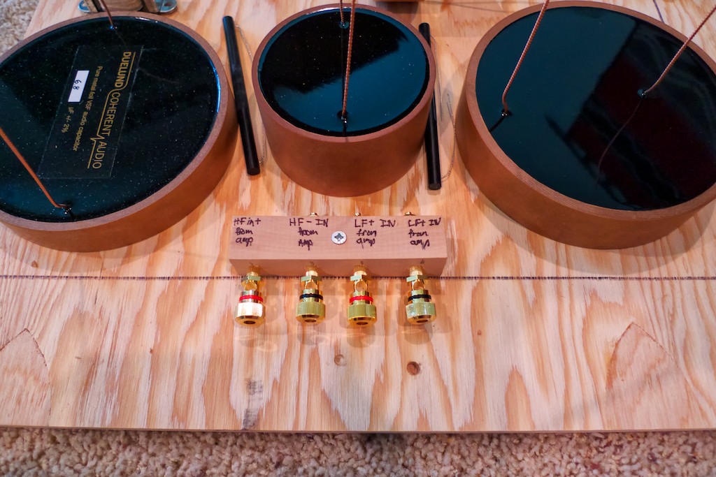
I wanted to maintain the adjustability (treble energy level controls & treble roll-off level controls) of the high frequency section of the crossover that is normally located on the front panel of the WRSE (photo above), so we relocated it to the outboard crossover, laying it out according to the high-frequency circuit schematic. We used copper setscrew lugs for direct wire-on-wire connections so there’s zero performance loss as compared with the stock adjustors. Wire-on-wire connections are better sounding than having the additional materials of intervening connectors that the signal has to go through. Pete recommended that we use straight-tongue copper setscrew lugs, 14-8 AWG, #10 stud, from McMaster-Carr, part number 6923K61.
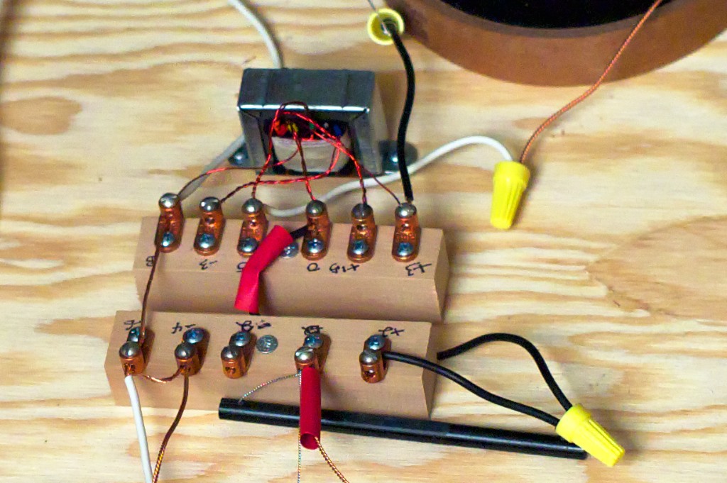
Above is a close-up of the breadboard version of the treble energy & treble roll-off level controls for the high frequency section of the crossover. With this design I have to move the two lead wires with the red heat shrink around on the setscrew lugs to change the treble energy & treble roll-off settings, but maintaining the purity of the signal more than makes up for the nuisance of having to loosen a screw and move a wire.
Binding Post Bypass Method: One of Mark Coles’ suggestions was to use the binding post bypass method for connecting the speaker cables from the amplifiers to the crossovers, and the internal cables from the WRSEs to the crossovers. With the binding post bypass method, the binding posts are not in the circuit, they’re just used to clamp wires together from the crossover to the cables from the WRSE & the amplifiers, eliminating another potential signal degrading connector material from the signal path.
With the binding post bypass strategy, each crossover required 4 pairs of binding posts, or a total of 8 for both channels. You don’t need fancy binding posts with this strategy, as they’re not in the circuit, they’re just used as a clamp to clamp wires and cables together. I bought 10 pairs (2 spares) of the Dayton Audio BPA-38G HD Binding Posts from Parts Express at $7.94/pair.
It’s a little hard to see in the photo above, but the bare wires from the crossover go through the binding posts, and then the spade connecters from the amplifier speaker cables or the WRSEs’ internal cables are clamped directly to the wires, eliminating the signal degrading binding posts from the circuits. There are better close-up photos later in the article of the final design so you can see the details.
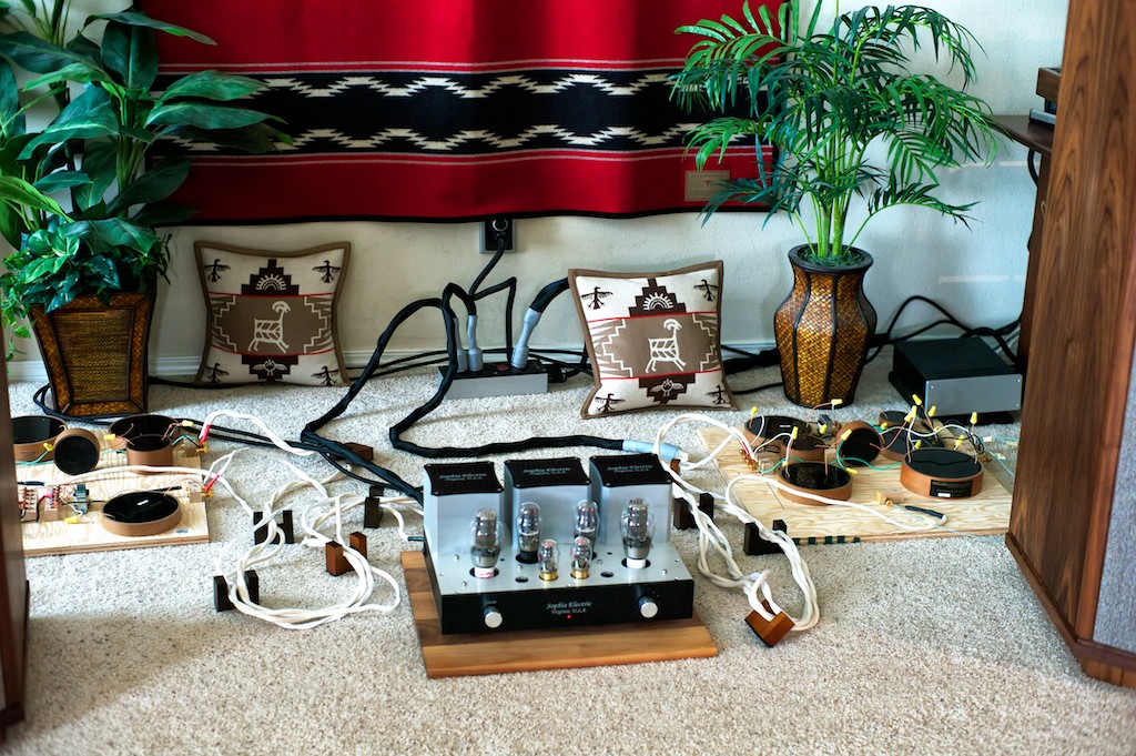
Testing the Left-Channel Breadboard Crossover: While unorthodox, it was actually quite illuminating to test/hear the left-channel Duelund breadboard external crossover while listening to the stock Tannoy right channel internal crossover at the same time. It was like listening to two different loudspeakers as a stereo pair, and then trying to characterize what the difference was between the two loudspeakers. The good news was that the test was a success - the left-channel Duelund breadboard crossover was functioning perfectly!
My first impressions were this: Oh my God – what a difference! In the most general sense, all the things that I know and love about my Westminster Royal SEs were intact, but enhanced to a remarkable degree. With the Duelund components the inherent voicing of the WRSE was retained, which is what I was hoping for, but the performance level was rather dramatically increased.
It’s always a little bit exciting/scary for me when I first fire up a system after having performed some modifications, not knowing for sure if there will be some unanticipated operational mishaps. When I first fired up the system to warm up, everything seemed to be ok, so I walked over to listen to the stock right channel WRSE, and then walked over to listen to the Duelund’d left channel WRSE. My heart sank – I couldn’t hear anything coming from the WRSE’s Dual-Concentric driver in the left channel.
I assumed there was a loose connection somewhere, so I put on an album and thought I’d jiggle wires until I figured out where it was. To my surprise music came out of both channels of the WRSEs, the Duelund HF & LF crossover was just so much quieter than the stock Tannoy HF & LF crossovers that I thought it wasn’t working, but it was – it was just very quiet with no music playing. I told Frederik about this result and he told me:
“I’m thrilled by your description. The silence is my main thing, as this really makes the music exist. Without silence there can be no detail. What you are hearing is the lack of resonance that was present in the old crossover, meaning that the speakers were never silent and never controlled.”
All I can say is that I was floored by the difference between the two crossovers, with the Duelund breadboard crossover being so quiet. The reduced noise level that results from the choice of materials and the resonance control of the CAST process that Frederik & Magnus use in creating the Duelund components works amazingly well, that’s for sure.
On the Duelund crossover’d WRSE side of the room there was a massive increase in the sense of recorded space and room ambience, which I suspect was contributed to greatly by the CAST inductors of the Duelund LF crossover. There was also a dramatic increase in transparency. The soundstage really opened up with something like double the depth, more natural height, and a very distinct layering of images back into the recesses of the soundstage. The images were solidly and naturally presented, with a lush sense of ambience and space around them. The stock Tannoy crossover sounded two-dimensional and opaque in comparison to the Duelund crossover.
It was a bit weird hearing this major positive transformation of the sound & musicality from the Duelund breadboard crossover on the left side of the room, while the right side of the room sounded … well not so good in comparison. I wouldn’t characterize the stock WRSEs as a bad sounding speaker - far from it! They are amazingly musical instruments as loudspeakers! However, with the Duelund breadboard crossover in place on my left channel Westminster Royal SE, it gave me a sense of what the WRSE loudspeaker was truly capable of, and it made me terribly excited to get on with the project.
As I said, the Duelund side was very quiet from a background noise standpoint. Particularly on good recordings, until an instrument comes in you almost think its not working, and then magically the instrument fills the room with music. The presentation of the music was also much more natural and relaxed sounding with the Duelund crossovers, and it felt more like music, if you understand what I mean. The stock Tannoy crossovers are harsh & edgy sounding in comparison, although I would never have characterized them that way had I not heard the Duelund crossovers, which sound so utterly natural and musical.
What the left-channel Duelund breadboard crossover did for the sonics and musicality of my Westminster Royal SE was quite impressive, because with the Duelund breadboard crossover in place there was a whole level of information that came through my West’ in terms of highlighting shades of tonal colors (more about this below), musically natural timbral detail, emotive qualities, and important and relevant sonic & musical information that just wasn’t there before with the stock crossover - it really is a big deal!
With the Duelund breadboard crossover there was also less sense of strain on dynamic peaks, and the dynamic contrasts across the dynamic range from softest to loudest were more discernable. Dynamic transitions to crescendos, decrescendos or diminuendos became revelatory with the Duelund bread crossover.
The Duelund crossover’s side also played louder without any harshness. It was a bit weird feeling my right ear starting to shut down on the stock Tannoy crossovers at a certain level of loudness, while the left ear was relatively unfazed and relaxed on the Duelund side. I wouldn’t have thought that could happen, but it did.
Ok, those were some of my first impressions for you from the left channel Duelund breadboard crossover test, and I’ll have a lot more to say about the sonic & musical attributes of the Duelund crossovers as this article progresses.
With a successful test of the left-channel Duelund breadboard crossover complete, I was more than a little excited about getting the right-channel Duelund breadboard crossover up and running!

In the right-channel breadboard I wanted to implement the following lessons learned from the left-channel:
- I wanted to optimize the layout of the Duelund components to make for a more compact design.
- I wanted to eliminate the mounting blocks for the treble energy & treble roll-off level controls and mount the setscrew lugs directly to the breadboard.
- I wanted to consolidate the mounting blocks for the binding posts.
With this in mind I laid everything out on the second piece of plywood breadboard (below).
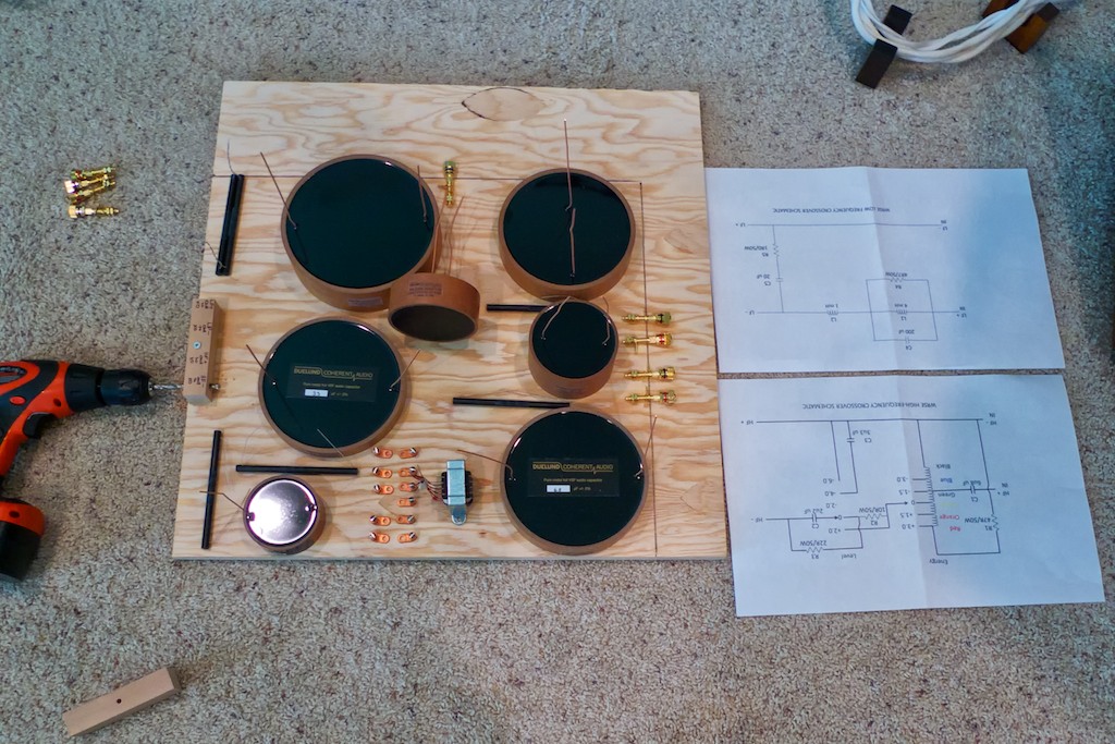
The two plywood breadboards for the left & right-channel are the same size (2-feet by 2-feet), but with a little careful positioning I was able to save quite a bit of space (the black lines show the new more compact size, compared to the original dimensions of the left-channel breadboard). The space inside the black lines is 18.5 inches by 20.5 inches, which is the same size as the vibrational energy dissipation platforms walnut top plate, which was my size goal.
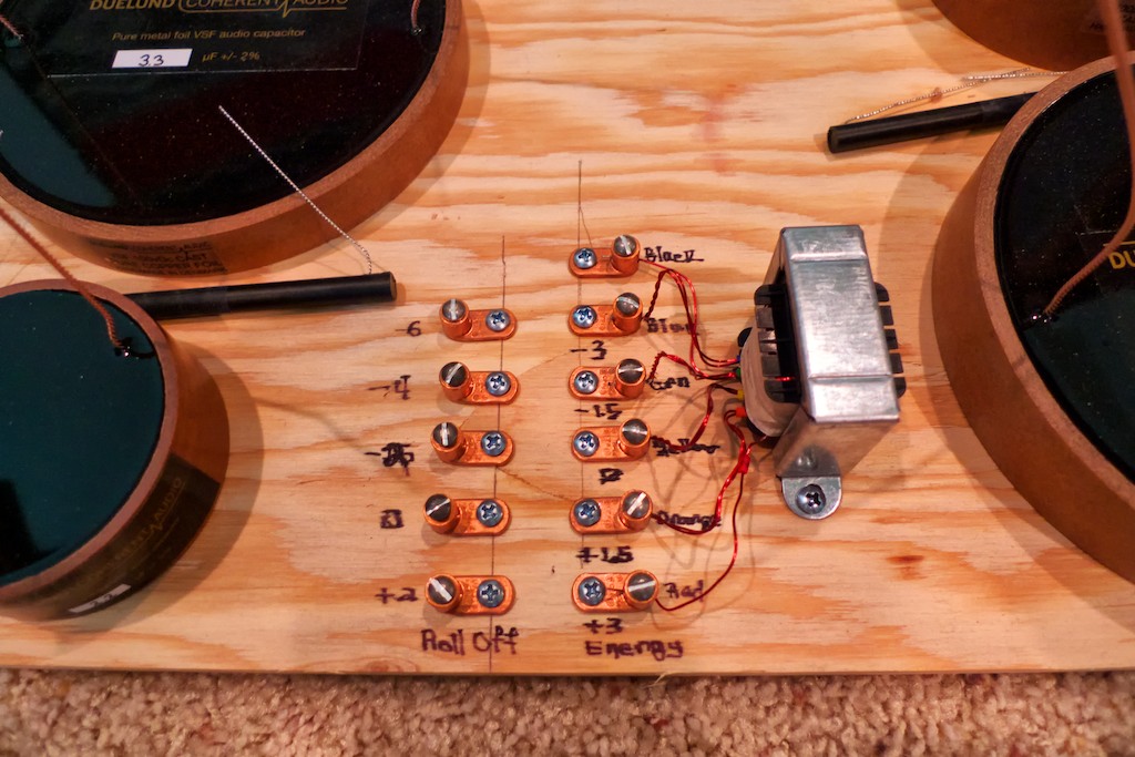
I also eliminated the mounting blocks for the treble energy & treble roll-off controls to mount the setscrew lugs directly to the breadboard (above).
Instead of using two separate blocks for mounting the HF & LF binding posts I used one block (above).
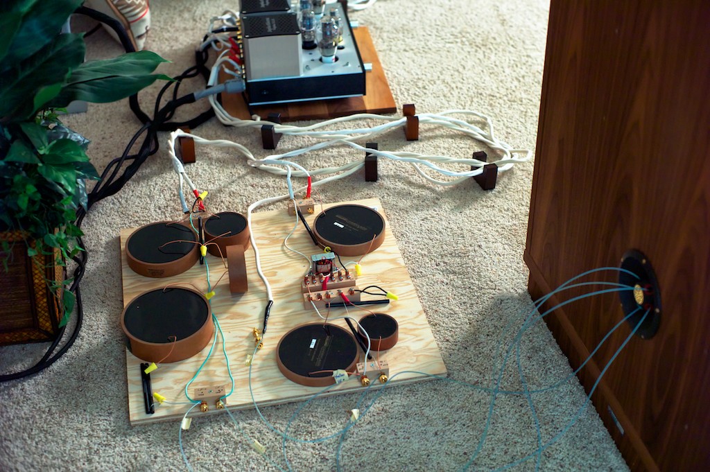
So when all was said and done, I had a complete right-channel Duelund breadboard crossover incorporating the lessons learned from the left-channel crossover (below).
The final step in the breadboarding process was testing the left & right-channel Duelund breadboard crossovers on the Westminster Royal SEs to make sure the circuits are working correctly.
I was really excited by the results I got when testing the left-channel Duelund crossover, so I was really looking forward to testing both channels with the Duelund breadboard crossovers. The results were pretty much what I was hoping for, with the right channel Duelund crossover functioning perfectly as well, and adding the benefits I heard from the left channel breadboard Duelund crossover to the right channel Westminster Royal SE loudspeaker.
I thought the performance transformation of my Westminster Royal SEs was breathtaking, and that was without any run-in time on the Duelund breadboard crossovers! Here’s a snippet from my listening notes recorded at the time:
“I’m sitting here listening to a new Chet Baker Quartet LP (photo below) I bought from Acoustic Sounds (Barclay Disques label) that is sounding so good it’s blowing my mind. Just before this I had my Analogue Productions test pressing LP of Bill Evans’ Waltz for Debby spinning on the ‘table and it was blowing my mind too. Ok that’s it for now, and I’m declaring today a complete success.”
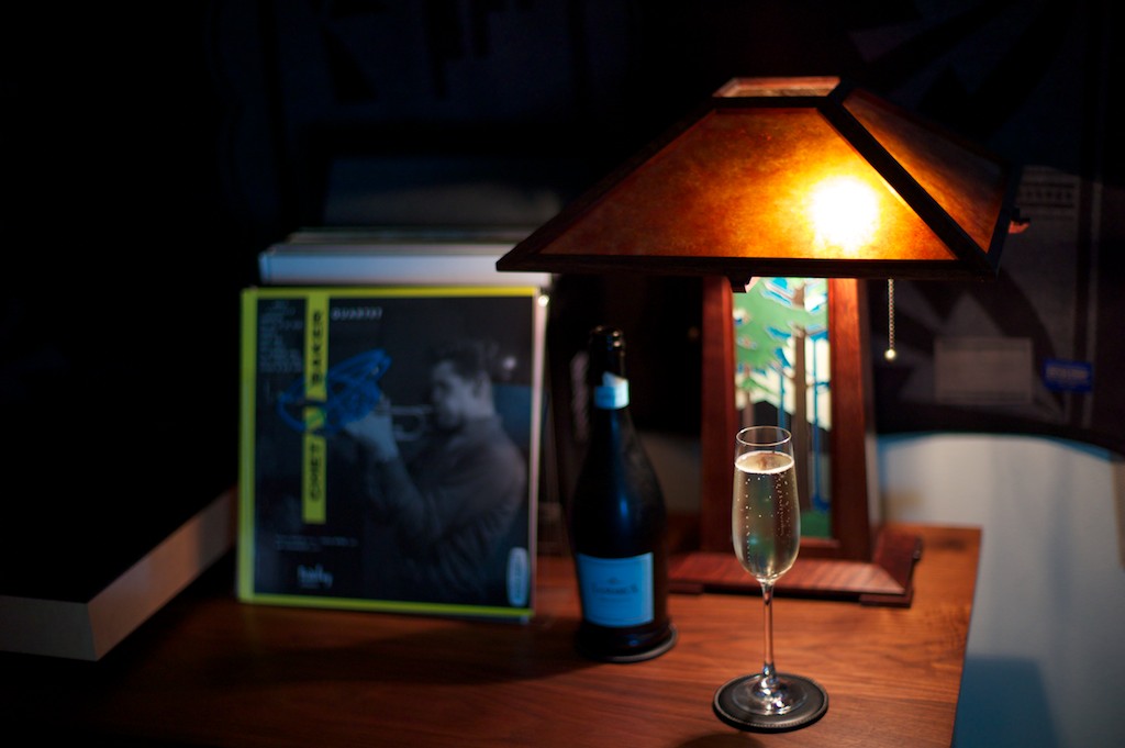
I was so pleased with the resulting improvement in performance to my beloved Westminster Royal SE loudspeakers from adding the Duelund CAST breadboard crossovers that I popped the cork on a bottle of Champagne to celebrate and took the rest of the evening off to listen to music and enjoy the fruit of my labors!
Ok, that's it for now my friends - stay tuned for much more soon!