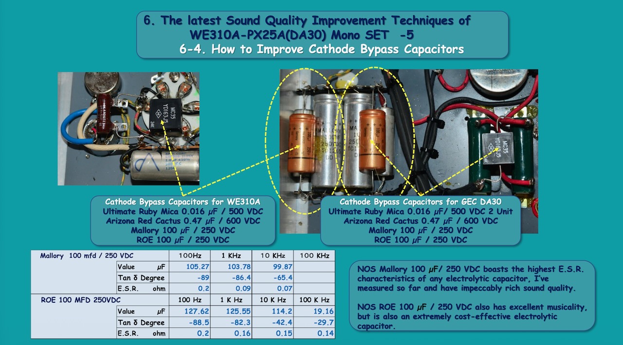
6-4. How to Improve the Cathode Bypass Capacitors
First of all, the role of this cathode bypass capacitor is said to be to restore the gain of the amplification stage, including this vacuum tube. This is because if only the cathode resistor were grounded, current feedback would occur, reducing the gain.
In fact, most tube amplifiers, including expensive models from world-famous brands, from vintage to the latest models, as well as parts kits and home-built amplifiers, use only one electrolytic capacitor of about 100 µF as a cathode bypass capacitor, soldered in parallel with the cathode resistor mentioned above.
However, it is no exaggeration to say that if you choose this capacitor, type, and value carelessly, you could miss out on maximizing the potential of your valuable tubes and output transformers. In other words, selecting this cathode bypass capacitor is one of the key points to achieving a truly realistic sound, I believe.
Now, leaving aside the complex theory of cathode bypass capacitors, I'd like to introduce better capacitors and various capacitor combinations to maximize the sonic potential of your tube amplifier. The first thing, regarding the physical properties of this capacitor, is to make it as close as possible to the properties of an ideal capacitance-only capacitor.
However, when it comes to electrolytic capacitors, generally speaking, the inductance component becomes noticeable in the mid-high and higher frequencies, for example above 7-8 kHz, and they no longer function as a capacitor at all in the high frequencies within the audible range. To cover these frequencies, that is, from the mid-high to the upper mid-range, and the highest frequencies, I connect a hermetically sealed oil capacitor in parallel with this electrolytic capacitor.
Furthermore, I also connect an Ultimate Ruby Mica in parallel to improve sound quality from the high frequencies to outside the audible range. By connecting three types of capacitors in parallel in this way, it is possible to create a capacitor with extremely low E.S.R. (Equivalent Series Resistance), or one with characteristics approaching those of an ideal capacitor across the entire audible range, and even into the high-frequency range far beyond the audible range.
My second recommendation is that you don't just stick to 100 µF, but try values several times higher. In this case, I connected two types of 100 µF capacitors in parallel to get a total of around 200 µF, which achieved a richer bass sound. The reason I chose two types was because I wanted to utilize the merits and characteristics of each electrolytic capacitor to improve sound quality.
I also tried constructing both the driver stage and power stage cathode bypass capacitors using identical components. Until now, I've often used expensive wet tantalum capacitors in the driver stage, but I've decided that it's entirely possible to replace them with high-quality electrolytic capacitors, hermetically sealed capacitors, and Ultimate Ruby Mica capacitors connected in parallel.
The specific capacitors I chose are the NOS Mallory 100 µF / 250 VDC and ROE 100 µF / 250 VDC, and new capacitors Arizona Red Cactus 0.47 µF / 600 VDC and Ultimate Ruby Mica 0.016 µF / 500 VDC.
In addition, I believe that this Mallory 100 µF /250 V is an electrolytic capacitor that was once used as a cathode bypass capacitor in tube communication equipment for the US military. I have measured the E.S.R. and Tan δ of a lot of electrolytic capacitors, and this one boasts by far the best measured values and also superior sound quality.
Well, my attitude, or rather my perception, of choosing capacitors with lower E.S.R. throughout the audible range also applied to the capacitors of the plate power supply and the associated decoupling capacitors.
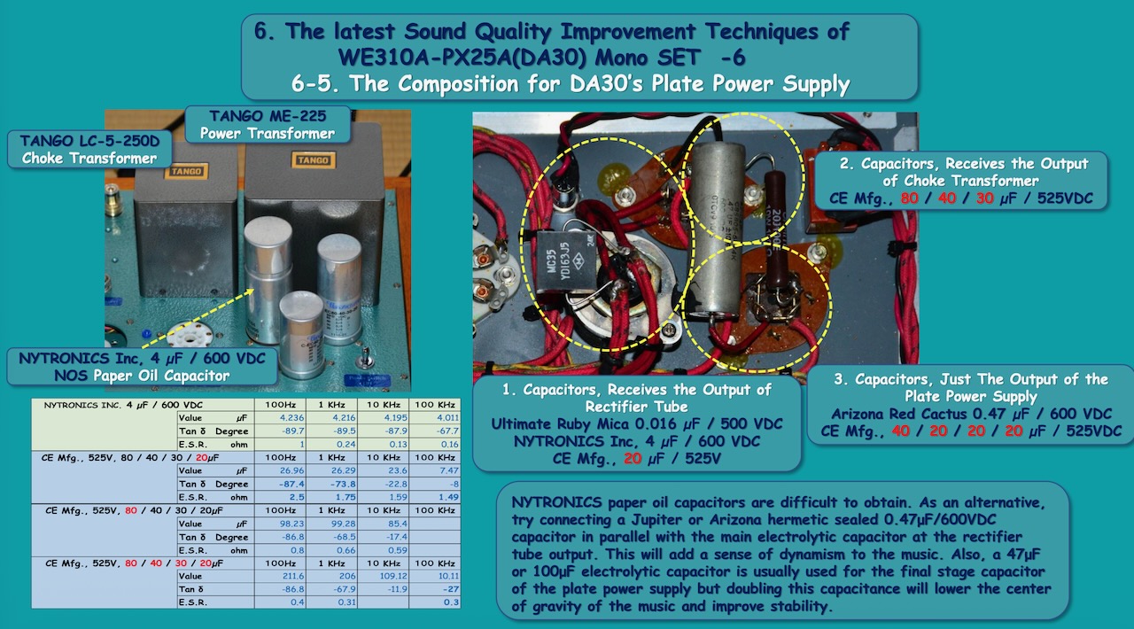
6-5. The Composition of Capacitors for DA30’s Plate Power Supply
The plate power supply for this amplifier faithfully follows the circuit design of my master Anzai-san, and uses a rectifier tube with condenser input type. As you know, there are two types of rectifier tubes: indirectly heated and directly heated. Personally, I much prefer the sound quality of directly heated rectifier tubes.
In the latter half of my life, I’m thankful enough to enjoy the ultimate vintage directly heated rectifier tubes below. Of these, I consider the three that stand out as having the best sound quality: the aforementioned WE274B, the British-made GEC (Marconi, Osram) U52, and the STC (BRIMAR) 5R4GY (4274B).
Each has such excellent sound quality that it's difficult to rank them in order of merit. But I could be quite fickle, so I thought it was a real luxury to have three different rectifier tubes to choose from depending on my mood that day. Anyways, my fortunate encounter with these historically valuable directly heated rectifier tubes came about while we were working together on the creation of this Ookubo-san's DA30 mono SET.
This could be said to be one of the fruits of my friendship with Ookubo-san, who has always pursued cutting-edge musicality. Indeed, I later found the intelligently bright tone of the U52, made in the UK, and was able to enjoy its fully relaxed and attractive sound for over 10 years, largely thanks to Ookubo-san's influence. In that sense, I am truly grateful to Ookubo-san, who had continued to pour his passion into the fascinating world of his “Rectifier adventure”.
Now, when using directly heated rectifiers with capacitor inputs, there are some things to be aware of regarding long-term reliability. Directly heated rectifier tubes are vulnerable to peaks in current (inrush current) flowing into the capacitor. If the maximum capacitance listed on the data sheet is exceeded, a spark (arc discharge) will occur inside the rectifier tube, damaging the rectifier tube.
In the case of the WE274, that value is a fairly small 4 µF. This value seems too small considering the inherent rectification effect at this stage, and the question becomes what the actual or practical maximum value is. From my experience so far, I have concluded that there are likely to be no practical reliability issues with any directly heated rectifier tubes at around 30 µF.
Another thing to consider when striving for high sound quality is the fact that the capacitor that should first directly receive the output of this rectifier tube should be one with as low an E.S.R. as possible across the entire frequency range.
To be honest, as mentioned in the section on cathode bypass capacitors, electrolytic capacitors have problems with their characteristics in the mid-to-high range and above, regardless of their capacity.
So, the capacitors I used to make up this group are as follows. First, I connected in parallel an Ultimate Ruby Mica 0.016 µF and a NOS NYTRONICS INC. 4 µF / 600 VDC paper oil-filled capacitor, which was formerly used in US military equipment and was made for this exact purpose.
I then connected in parallel the 20 µF from CE Mfg., 525V, 80 / 40 / 30 / 20µF, to get a capacity of around 30 µF. I chose these American-made multi-section can capacitors because they are manufactured to the same specifications and on the same production equipment as the original Mallory capacitors, and because they are secured with twist locks via Bakelite insulators. Since electrolytic capacitors are susceptible to sound modulation due to external mechanical vibrations, I thought that the Bakelite insulators might have the potential to block or dampen chassis vibrations.
The output of this group of capacitors is led to a choke transformer, TANGO MC-5-250D, and its output is input to the following capacitors, forming an LC type filter. This is a parallel connection of the remaining 80 µF, 40 µF, and 30 µF capacitors from the CE Mfg., 525V, 80 / 40 / 30 / 20µF multi-section, resulting in a fairly large capacitance of 150 µF nominally.
Furthermore, even though each capacitor is the same multi-section, the tonal balance in the low and mid-high frequencies is slightly different. By connecting 80 µF, 40 µF, and 30 µF capacitors in parallel, we can significantly reduce the E.S.R., increasing the dynamism of the music and further smoothing out the tonal characteristics and quirks of each capacitor.
Next, the output of these capacitors passes through a wire-wound resistor of approximately 100 ohm / 10 W and is input to the next multi-section capacitor, CE Mfg., 525V, 40 / 20 / 20 / 20µF, with also connecting in parallel. And in the final stage of this plate power supply, a hermetically sealed oil capacitor, Arizona Red Cactus 0.47 µF, is connected in parallel with these electrolytic capacitors.
Of course, the purpose of this is to improve the power supply's response in the mid-range and above, thereby improving sound quality. Well, this resistor, 100 ohm together with the final-stage capacitor, 100 µF, forms a low-pass filter, but is primarily used to adjust the plate voltage of the DA30 power tube, setting it to a maximum of 480 VDC. The total current here is about 100 mA, so inserting a 100 ohm resistor will allow for a voltage drop of around 10 VDC.
As a result, the capacitor connected to the output of the choke transformer has a larger capacity of approximately 250 µF, compared to typical tube amplifiers in the market, which I believe contributes to the solid stability of the reproduced sound and it could be a very rich, powerful bass range. And one side of this power supply output is sent to the primary winding of the output transformer, and the other side passes through a voltage divider circuit to two decouplings for WE310A's plate and the screen grid.
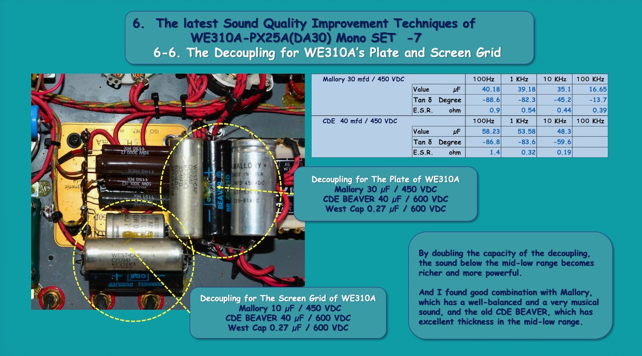
6-6. The Decoupling for WE310A’s Plate and Screen Grid
Decoupling can also be described as a local power supply. And the importance of the supply capacity and the quality of the local plate power supply for the WE310A voltage amplifier stage is easy to understand.
However, I believe that the importance of voltage stability of the screen grid (SG) of the WE310A, which is a pentode, deserves more attention. This is because fluctuations in the SG voltage are said to lead to operating point shifts and degradation of sound quality.
I have seen various examples of using the WE310A in DIY articles from “MJ” and others, and some have even used Zener diodes or voltage regulator tubes to stabilize this SG voltage. However, in my master, Anzai-san’s design, stabilization was accomplished very simply with only a single 10 K ohm / 5W “Bleeder Resistor”. There is absolutely no source of noise here, and it feels like it's in accordance with the laws of nature. I think this is a concrete example of the hidden but excellent design of this DA30 mono SET.
Now, the original WE310A's local power supply to the plate used a Mallory 30 µF / 450 VDC. The WE310A's SG power supply also used a Mallory 10 µF / 450 VDC, as designed by Professor Anzai. However, this time I wanted to increase the capacitance of these capacitors to improve sound quality. And so, connected in parallel to these Mallory capacitors were CORNELL DUBILIER, BEAVER 40 µF / 450 VDC, more than doubling the capacitance.
Furthermore, I also connected in parallel a hermetically sealed oil-filled capacitor, WEST CAP 0.27 µF / 600 VDC, to reduce E.S.R. in the audible frequency range. Well, the CORNELL DUBILIER BEAVER 40µF / 450VDC is a fairly old and rare NOS electrolytic capacitor housed in a cylindrical cardboard tube, but in my opinion, this type of capacitor has not only desirable sound quality but also excellent electrical characteristics.
Please click on the link below to get to the next page.