
I am delighted to be able to share with you Part 7 of Yazaki-san's adventure with his vintage Marantz Model 7K preamplifier!

Yazaki-san (center) with friends in Tokyo.
I always enjoy reading what Yazaki-san has written, and I always learn a lot from his many insights.
I would like to say a very special "Thank you!" to Yazaki-san for taking time to write this wonderful article about vintage Marantz Model 7 K preamplifier modifications, and sharing it with all of us here at Jeff's Place!
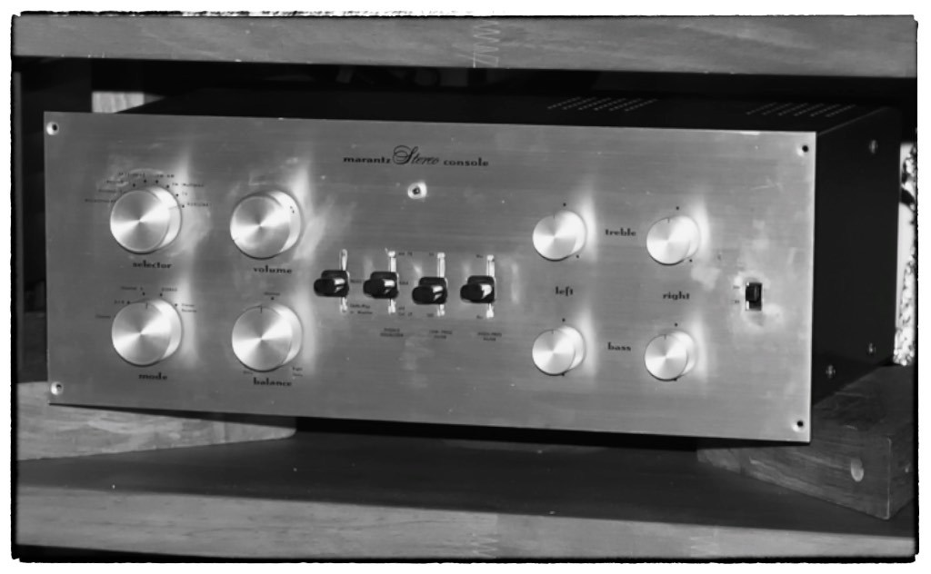
Yazaki-san's vintage Marantz 7k preamplifier.
¸¸.•*¨*•♫♪¸¸.•*¨*•♫♪¸¸.•*¨*•♫♪
The First Appearance of the Marantz Model 7 in Japan
I succeeded in getting a valuable magazine last summer after I wrote up “My Adventure with the Marantz Model 7, Part 6", which was the July 1979 issue of Radio Technology, another legendary Japanese specialty radio & audio technology magazine, just like MJ is.
This old issue from 1979 engaged my interest with its absorbing article about how to assemble the Marantz Model 7 K kit, titled “The Reborn of Fame, Model 7” by Isamu Asano-san.
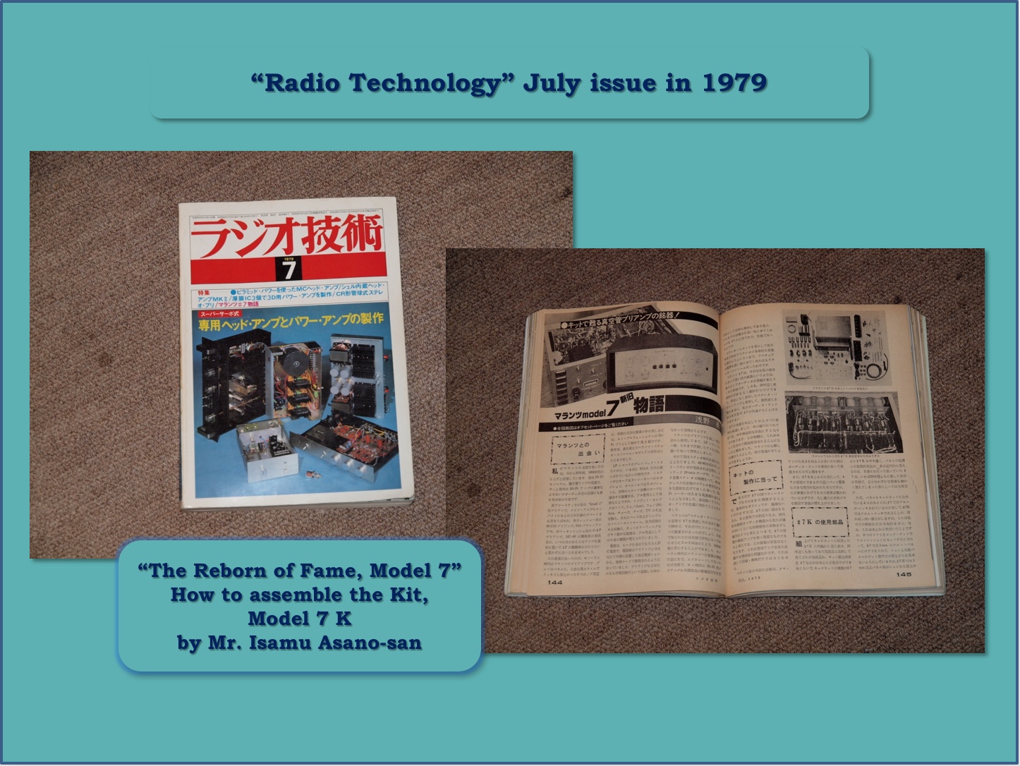
I already introduced Asano-san in Part 4, while referring to the masterwork of Asano-san, “The Fascinating Tube Amplifier, Its History, Design and Assembling”, published in 1971.
There Asano-san talked about the importance of the mica capacitor: “I installed a big size mica capacitor, but a lot of tube amplifier enthusiasts would think that it might be meaningless to use it, because there are a lot of types of high quality and reasonable size tubular oil capacitors. But once I heard the sound of this PX25 SET with highest quality speaker, I found out definite differences of the sound between the mica capacitor and tubular oil capacitor. If you doubted of my impressions, I would like to advise you to try it once“.
Yes, Asano-san truly guided my way of adventure into the world of mica capacitors, with unfailing interest up to this time, and so I owe much to him.
The July 1979 issue of “Radio Technology” shared his story about the first introduction of the Model 7 to the Japanese market, and I was impressed with how Asano-san had long loved and used his Model 7.
The Marantz Model 7 preamplifier had already earned its place in audio-history, being released in 1958, but for the Japanese market it was first introduced in the August issue of Radio Technology in 1962, three or four years after the USA market.
That seems like too long of a time for an introduction from the view of the present global market, but I remember well the year of 1962 in Japan, when we were still struggling to get out of the days when the economy was still like a developing country.
I can recall clearly when I was 15 years old and in junior high school, I asked my father to take me to the movie Blue Hawaii starring Elvis Presley. I was so impressed with the numerous beautiful scenes of Hawaii with its rich civilization and life, which was another world from Japan in those days, but also the marvelous songs of Elvis, and his vocals with phrasings that were full of rhythmic sensibility.
As a personal note, it was fortunate luck that just one month before the publishing of the July issue of Radio Technology in 1979 that I had a chance to visit and stay in Oahu and Kauai during our honeymoon, where they filmed scenes for Blue Hawaii.
As I mentioned in Part 1, at that time Japan was already counted among the advanced nations of the world, and it was when I also started my career as a mechanical engineer, working at Pioneer. Anyway, when I look back to my younger days, that haunting encounter with the music of Elvis Presley might have been something of a catalyst for me in proceeding to be an audio engineer from an audio hobbyist.
I must return to the article by Asano-san, “The Reborn of Fame, Model 7”: I recognized that it was Asano-san who first introduced the technology of Marantz Model 7 to us in Japan in the November 1962 issue of Radio Technology.
Asano-san had managed to get a Model 7 of his own at that time, and he talked passionately about how the Model 7 preamplifier had guided him to its true significance in audio.
When he saw, heard, and made measurements of the Model 7, Asano-san recognized the limitation of his own skills, and he gave up on building a preamplifier of his own design from that moment on, and instead fully enjoyed listening to stereo long-playing records through his Model 7.
During the 17 years from 1962 to 1979 that the Model 7 had been his reference preamplifier, Asano-san devoted himself to designing and building power amplifiers with vintage tubes from all ages and countries, with the theme of his lifetime being the completion of an endless number of amplifier designs.
Now we can see those power amplifiers in his masterwork, “The Fascinating Tube Amplifier, Its History, Design and Assembling”, published in 1971 as an MJ special edition.
Of course, I was so encouraged by Asano-san's words, because I have long respected him as a true tube amplifier enthusiast and lover, and he had a sincere respect for the Model 7 as his favorite preamplifier, just as I have long loved my modified Model 7 K.
My Latest Experience Modifying the Marantz Model 7 K
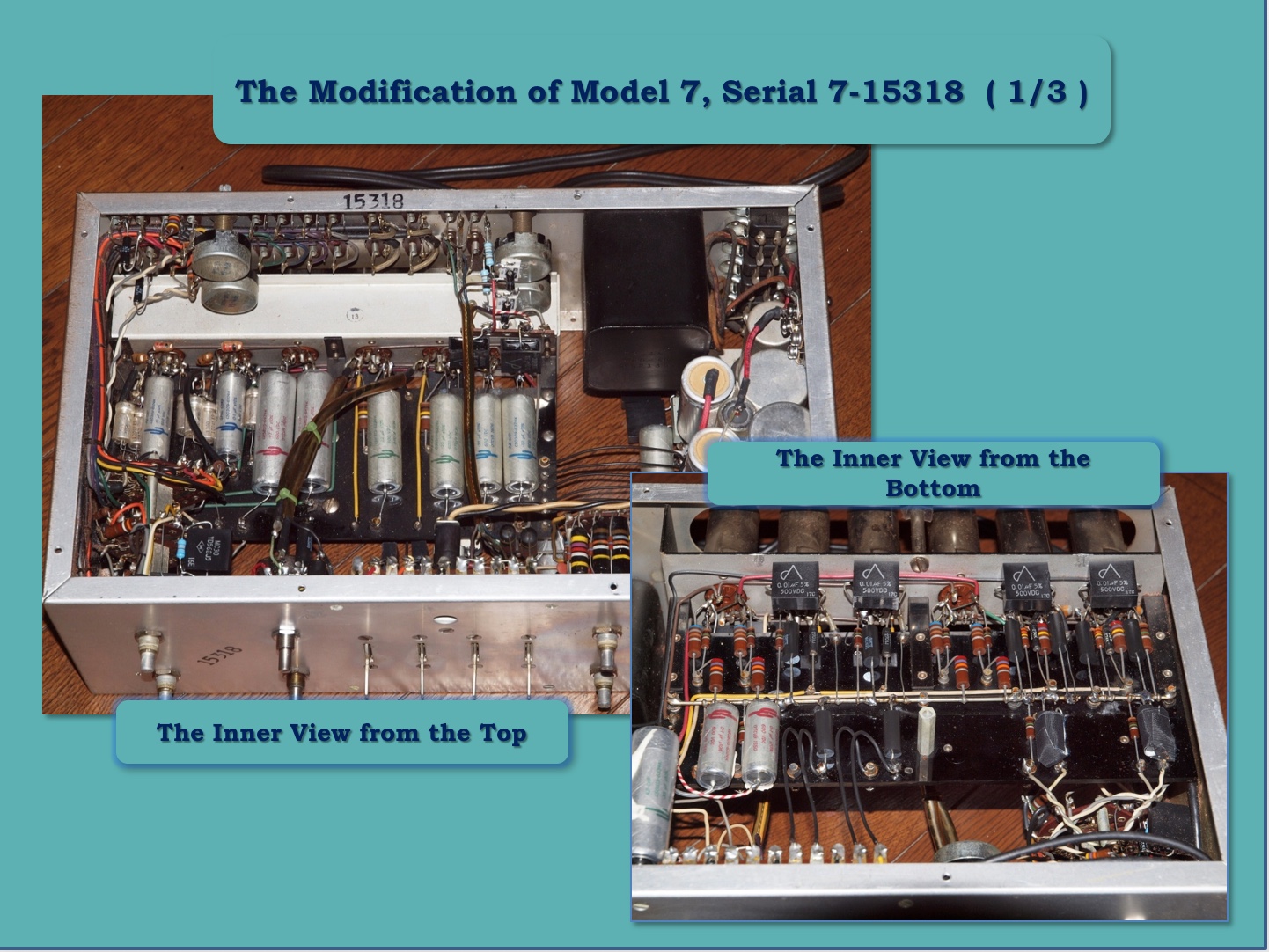
Fortunately enough I had a chance to experience one more modification with Alan-san’s early production Model 7, serial No.15318.
Alan-san has also been one of Jeff’s Place eager readers, and we personally have built a very favorable relationship with each other as kindred spirits for the audio hobby in the last few years.
Alan-san's Model 7 was delivered to me towards the end of last August, and to tell the truth, Alan-san had also asked me to build up a DA30 (PX25A) monaural SET more than one year ago, so I made up my mind to do my best job for the modification of his preamplifier, and to match it well with his valuable vintage tube mono SET amplifier.
Anyway, I have regarded myself simply as an audio craftsman, and I didn’t want to run over in the same way, but still I wanted to try and search for challenging new improvements to the Model 7.
Therefore, in Part 7, I’d like to share some of my modification methods, and I also want to tell you about uncovering the true potential of the famous RIAA EQ of the Model 7 using high-precision measurement data with the valuable help of Kato-san, my old best friend.
I imagine that such data would be desired by and intriguing to Jeff’s Place readers.
New Improvement of the Power Supply
For the modification to Alan-san’s Model 7 I had searched for the highest quality of power supply, which would be proud of the minimum noise revel, which I had never experienced before.
I described in Part 2 that there are two major points to the quality of power supply, one being the noise figure, and the other being the speed of the current from the power supply.
The noise figure decides the noise level of the signal current, and it mainly owes to the characteristic of the diode used for rectification.
The +B rectification scheme of the Model 7 is half-wave and it would be positive for the sound quality rather than effective full-wave rectification because of the lower noise level or the simpler noise spectrum with only one diode. Luckily, I came across a diode with almost perfect characteristics, the STTH6112TV2 (TV1), an Ultra-Fast & Soft Recovery type, in early 2010.
I feel the sound quality of this diode is just as remarkable as vintage direct-heated rectifiers, because of its huge & clear sound stage and the outstanding flat energy balance from the highest-range to the richest low-range.
In these circumstances, I became aware that, even if the STTH6112TV2 might be nearly free from the switching noise, that in principle there would be some level of remaining noise spectrum through the rectification with this diode.
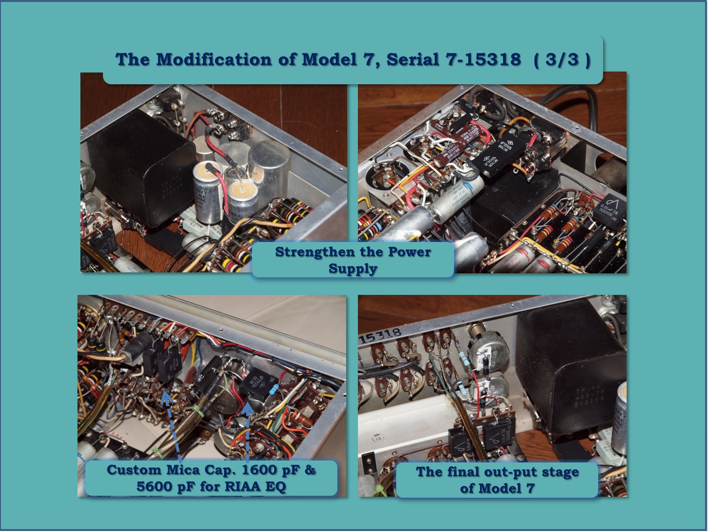
I decided to install high quality mica capacitor into just the DC output of STTH6112TV2 for +B rectification, so that this switching noise would flow to the ground as much as possible.
Furthermore I also changed to a pair of STTH6112TV2 as a bridge diode as a luxury for the heater rectification, and put the mica capacitor in the output of bridge for the same reason.
About the heater rectification, it must be true that ECC83(12AX7) is only a indirectly-heated tube with a separated heater and cathode, so that the quality of the rectification current would not have so much effect on the final quality of the sound compared to +B rectification.
But I dared to try such ways of the heater rectification for eliminating this switching influence into relative minimum. In addition, the value of the mica capacitor would be sufficient around 10,000 pF and usual dipped mica capacitor could be effective, I suppose.
Well, concerning the modification of Alan-san’s Model 7, the main volume had been already changed to an Allen-Bradley from the original Clarostat. Unfortunately, the Allen-Bradley was not in good condition, and so I had no other choice but to look for a replacement 500K ohm volume control like the original Clarostat double volume type. Fortunately enough, I came across a desirable sealed volume control for use in measurement equipment made by Tokyo Cosmos in Japan, the RV30YG 250K 2-A.
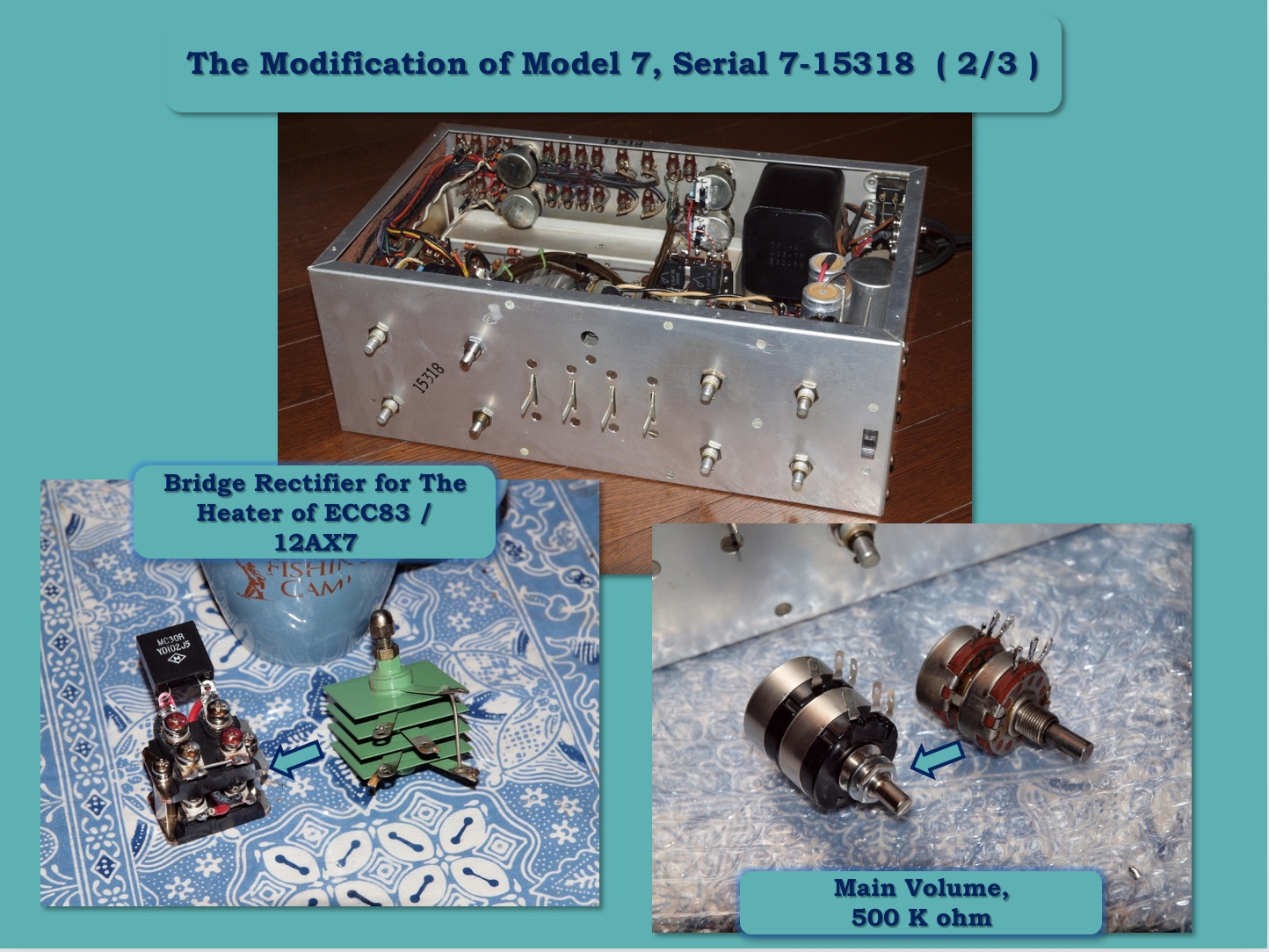
My Model 7 K has been equipped just this same volume control from the beginning, and I have enjoyed the highest reliability and sound quality with the RV30 for nearly 40 years, so I did not hesitate to adopt it.
They say the original Clarostat volume used in early original production Model 7's sounded very good, but to be frank, I don’t feel there are any disadvantages in using the Tokyo Cosmos compared to Clarostat based on my past experiences.
Well, I’d like to point out the one more exceptional and superior circuit design aspect of the Model 7, compared especially to the usual semi-conductor preamplifiers. The high level output from a CD player, DAC, tuner, or phono EQ, is selected and then accepted by the balance volume with the higher value resistance of 1M ohm, and next the main volume control of 500K ohm in the Marantz Model 7.
Generally speaking, handing over the signal on an unbalanced circuit, the higher input impedance on the subsequent stage would be better for lower loss of signal. Usually, the output impedance of the previous stage, such as a CD player, DAC, or tuner would be 1 K ohm or below, so 1M ohm or 500K ohm is surely high enough a largely lossless signal transmission. To conclude, Model 7’s tone amplifier could bring out the full potential of any source component, I believe.
Anyway, I completed and enjoyed the restoration of Alan-san’s Model 7 early last November with almost all the modifications described in Part 1 to Part 7. But how was the result of these modifications for the owner of this Model 7?
I’d like to share Alan-san’s impressions below, and I was so delighted to hear from him!!
“I am really enjoying and loving the modification that you made for my Marantz Model 7. The sound is simply so fluid, organic, and real … expressing textural tones that resonate well within one’s unconscious. There is a sense of being able capture the essence of allowing a chance at stepping off of the temporal plane and the resultant framework of Chronos, while facilitating a fall into an orientation of sitting squarely at the expansion of a moment under the influence of Kairos … lost listening, feeling, and breathing the music … Real Sound.“
The Uniqueness of the Marantz Circuit
I found a pdf file titled “Marantz-Audio history Library” on the web. In the article, is provided the description of Model 7 below:
“In December of 1958, a true stereo preamplifier, the Model 7 was released. The circuitry was basically different from most preamplifiers of the day as the Model 7 used a unique three-stage phono preamp/equalizer that later became as “Marantz Circuit””.
In Japan, I remember well, there was so much argument about the superiority of RIAA equalizer circuitries, between McIntosh C22 and Marantz Model 7 throughout the 1970’s in Japan.
With this background, I suppose, that each preamplifier was far superior in sound quality with full musicality than other preamplifiers at the time, but there were also a lot of amateur tube enthusiasts who enjoyed making their own preamplifiers at that time.
The main writer of “MJ” from 70’s to 80’s, Morikawa-san (I already introduced him in Part 1), advised us that “if we had a chance to build up the preamplifier with phono EQ, we had better try the C22 type circuit design with P-K feed-back through two-stages".
He said that this circuit would be very stable, more free from the risk of oscillation than the “Marantz circuit”, and so it could be easily built up and function successfully for amateur enthusiasts.
I also agree his advice might be right, because I had actually tried to assemble the phono EQ, just imitating C22 type design by myself, and enjoyed the sound before I completed the assembling of the Model 7 K in early 1980.
In strictly technical terms, Kato-san, my best friend, already explained about each phono EQ design in the figure on Part 2, “Comparison of Tube Preamplifier, especially in their RIAA phono equalizer circuits”.
Here it is: “Features of the Model 7: As V1’s and V2’s load are identical, their cutoff (pole) frequencies overlap, thus there is sharp fall-off (-12dB/Oct) that may influence its stability by an eventual deep NFB; hence a compensation capacitor (V2p to V1k, C67: 22 pF) should be critical to cope with it ... . On the other hand, features of the C22: As V1’s and V2’s loads are different, their pole frequencies don’t overlap, thus it is more stable by NFB ... .”
Well, I suppose we could find out the engineers' challenges and the specific results of how to cope with cutting off the risk of oscillation.
For example, in the actual circuit of original Model 7, for V1’s load, R65: 274 K ohm, a custom deposited carbon resistor with precise value by CGW, for V2’s load, R69: 270 K ohm (a little bit staggered value of V1’s load) Allen-Bradley carbon composition are each adopted and for the very critical compensation capacitor, C67: 22 pF is installed into the well-studied position, very close to the pins of V1 and V2, ECC83 (12AX7).
For a comparison of sound quality to the C22, as far as I have seen and heard in Japan, the discussion had converged gradually in favor of the superiority of the Model 7 through the long years. One of the evidences of this could be found in the current prices of used Model 7's on web auction sites. You can see the price of early production Model 7's in good original condition would be very high, just as if it were a treasure or valuable antique to a collector.
Summing up, the geniuses at Marantz took severe risks in challenging an unstable circuitry, yet they achieved a highly sensitive and very lively sounding phono equalization with full musicality, something that we had never experienced before. They truly succeeded in completing an exactly unique “Marantz circuit”, and can you believe it, this was a design achievement from over 60 years ago!
The Accuracy of RIAA Deviation and Its Beautiful Curve
Now I’d like to share with you the true potential of the Model 7’s RIAA phono EQ after we modified Alan-san’s original using the precision measurement data by Kato-san.
I changed a few RIAA parts: For C15 I changed the 5600 pF Bumble Bee in the selector to a custom mica capacitor with a very precise value. For C10 I changed the 1600 pF ceramic capacitor to our custom mica capacitor. For R15 I changed the 680K ohm Allen-Bradley carbon composition resistor to a metal film resistor with precise value. For R64 I changed the 511 ohm CGW deposited carbon resistor to a special made one by myself, composed of a parallel connected Tepro RA, 1K ohm / 1W and Ohmite WH 10 ohm. In addition, the R64 resistor is critical for getting lively timbre, in my experience.
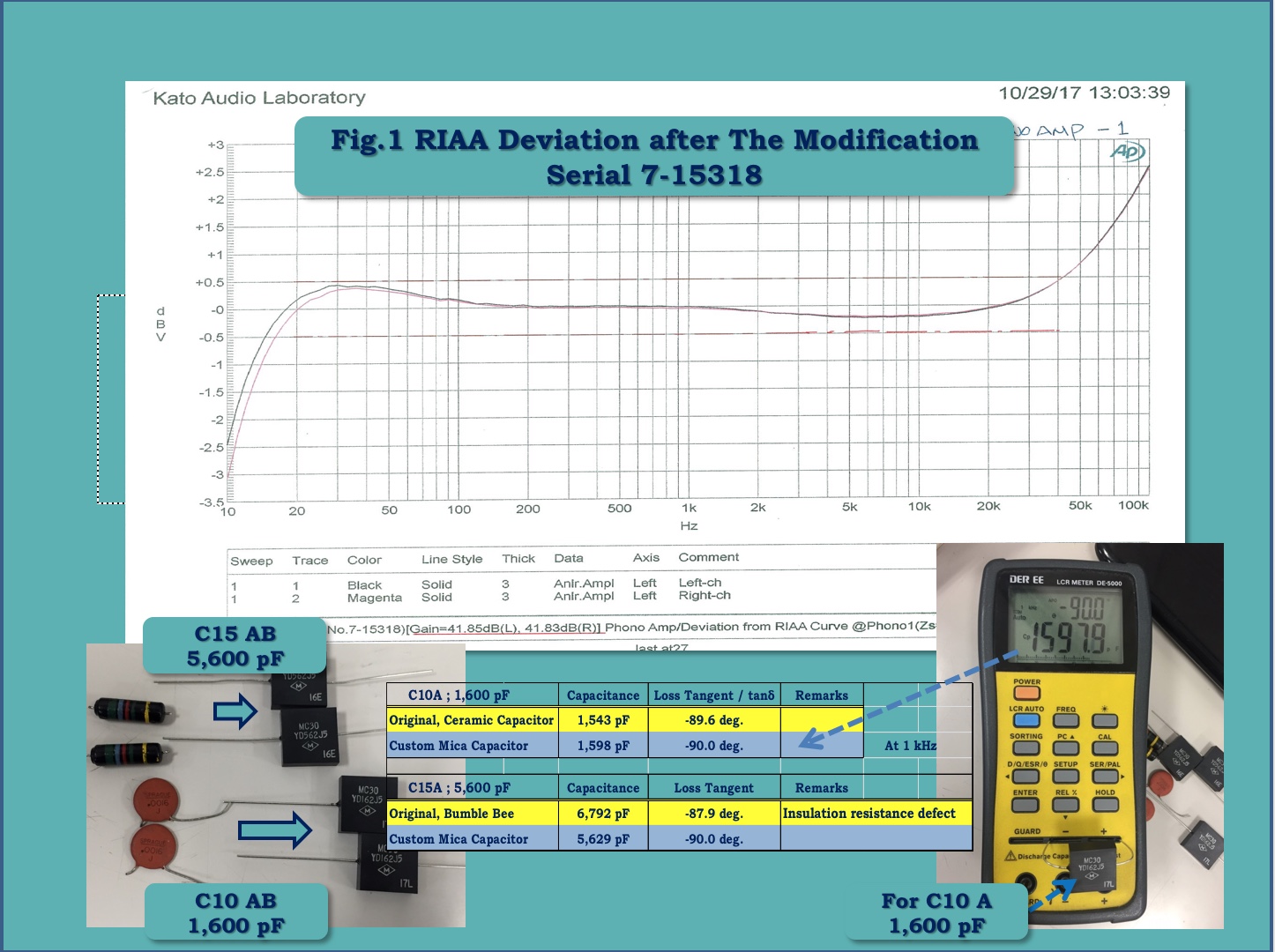
When you look at the measurement data in Figure 1, you find out right way its “RIAA deviation characteristic” is very precise and its a beautiful curve.
Furthermore, the gain (each channel: 41.85 dB, 41.83 dB) and the deviation of each channel are plotted just on the one line. I believe this deviation characteristic would be just the same as the originally targeted one by the fabulous Marantz’s engineers.
I changed the parts using very precise values according to the Model 7’s circuit diagram. First of all, I’d like to point out the flat response, from 200 Hz to around 1 KHz, is very important for high-fidelity reproduction with much musicality, because over half the energy of the music concentrate this mid-low and mid frequency range.
I suppose that the slight dent of mid-high range around -0.2 dB might be rather desirable for our hearing sense. Generally, the flat response sound is not favorable to our hearing because that our hearing is too much sensitive at 2 or 3 KHz, so this slight dent might be desirable for our natural hearing sense. In other words, the slight dent would bring out the tonal quality, but it would not be too harsh.
The rising high-frequency end would compensate the high range response of a cartridge, especially a MM type, and also add an expansive and airy sound-stage, I imagine.
Well, about the -2.5 dB or -3 dB at 10 Hz, please don’t have any concerns about that value. Generally or inevitably, there is the mechanical resonance of the compliance or the stiffness of the cartridge’s vibration system, made up of the stylus tip & shank, magnet or coil, some kind of damper, and the total moving mass or inertia of the tone-arm and the body of cartridge. And these resonance frequencies of usual cartridges and tone-arms remain in existence at just 10 Hz and under. Of course, it would fit well to prevent the harmful effect from the ultra low frequency resonance, with no relation to the out-of-band musical signal on a vinyl record.
The Superb Noise Characteristic
The residual noise level is just the denominator of the “Signal to Noise Ratio”, and so is a very critical figure or characteristic of the RIAA EQ like the RIAA deviation is, and it would appraise the quality of the sound reproduction with vinyl records.
When you combine the two factors in a tube amplifier, the higher RIAA EQ gain, over 40 dB for MM cartridges, and the minimum residual noise level would be one of the hardest tasks for the analog circuit designer in the present-day.
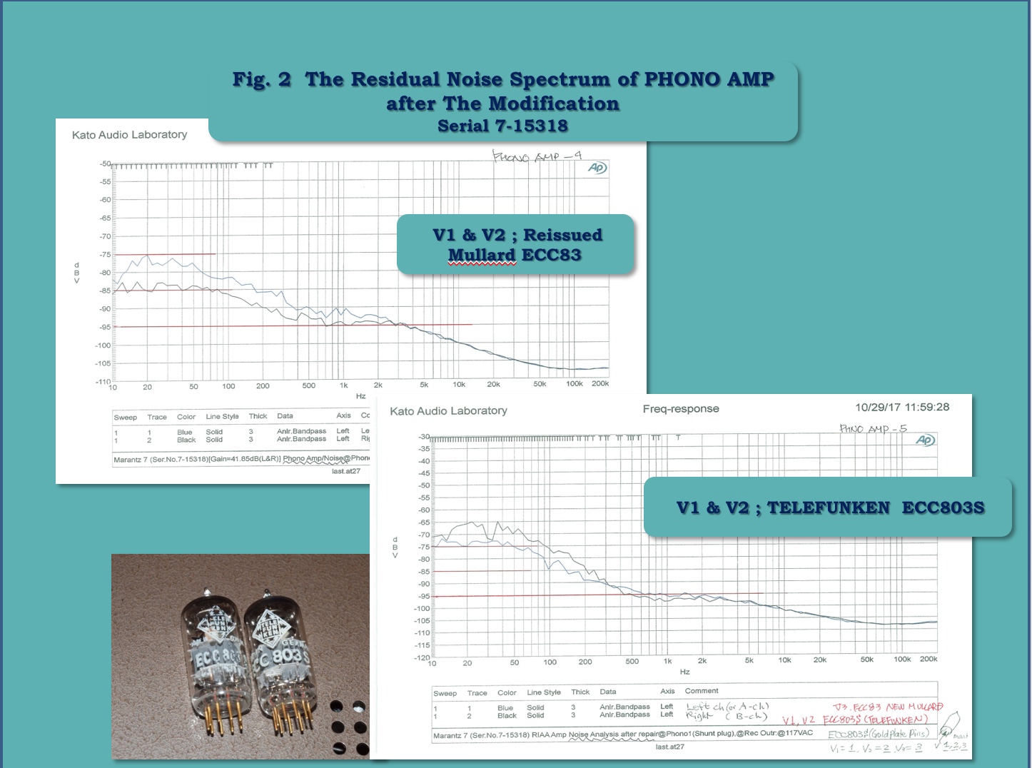
Please refer to Fig 2, “the spectrum of residual noise”, using reissued Mullard ECC83, Russian tube, for V1, V2 and V3.
The noise level of 1 KHz is recorded -91 dBV (Left) and -94 dBV (Right), and it means the equivalent input signal-to-noise ratio is at the amazing level of -132.85 dB (Left, -91+(-41.85)) and -135.83 dB (Right, -94+(-41.83)).
When using vintage Telefunken ECC803S for V1 and V2, the level is reached at the incredible high level, -139.85 dB (Left) and -137.83 dB (Right).
I suppose these measurement data might be very close to the maximum level of tube phono EQ designing, and of course they assure us the highest quality reproduction of an analog record.
Also, I’d like to reveal the sound differences between reissued Mullard ECC83 and Telefunken ECC803S at this time.
To tell the truth, I have long used this ECC803S, installed in my old Model 7 K, more than 10 years without any senses of frustration. I suppose you might have known well that Telefunken ECC803S is the so called “Holy Grail”.
But is it worth managing to get the tube? It must be a hard question also for me at present, but the comparison with the reissued Mullard, I felt the musicality of the old ECC803S was truly far superior to the reissued tube despite its disadvantage of low range noise spectrum. And its deep tone was so attractive for my hearing. Yes, the tone might have the true flavor of a typical excellent vintage tube, I realized.
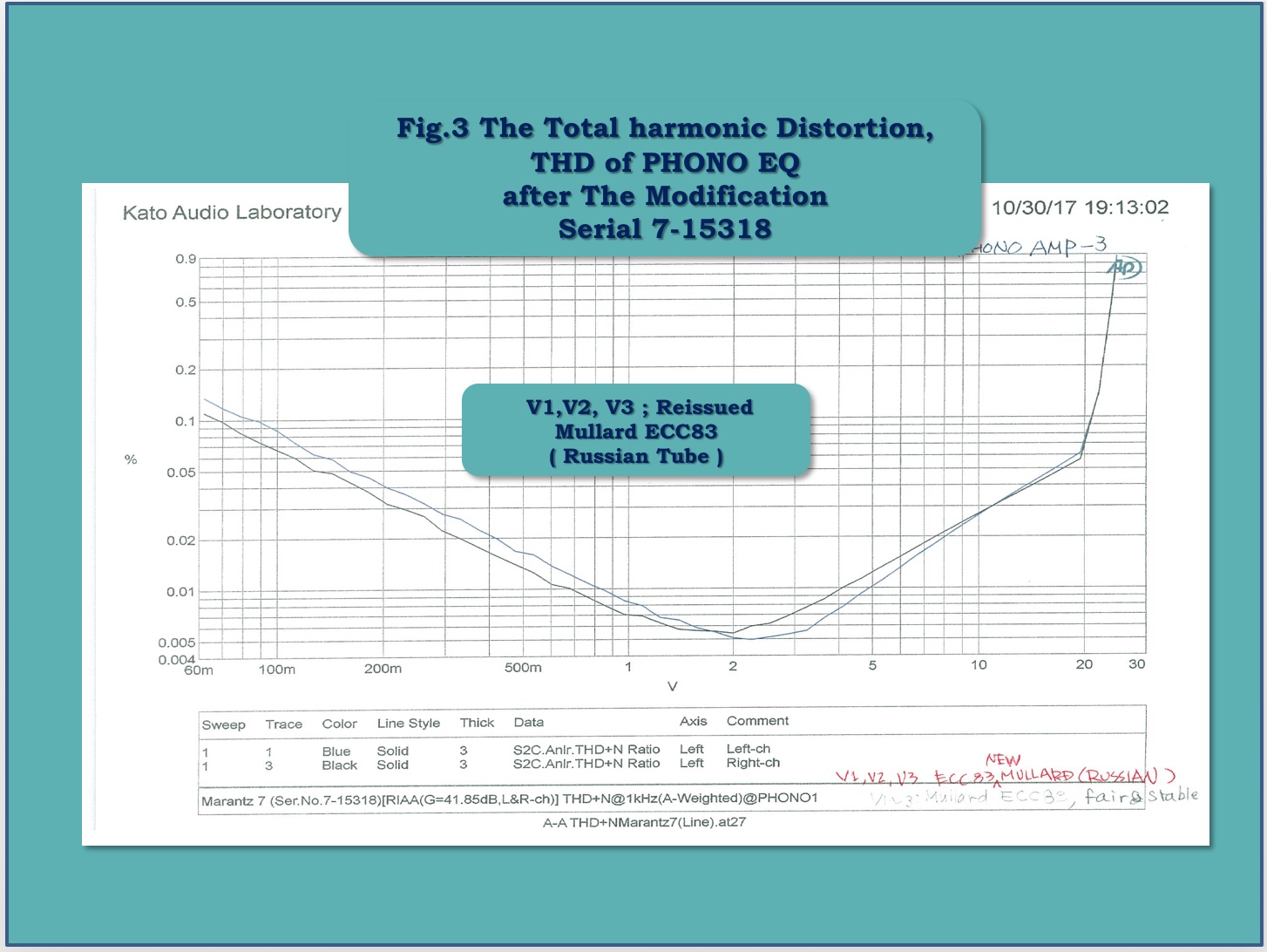
Please refer to Fig 3, “The total harmonic distortion of PHONO EQ”.
Usually, the out-put level of phono EQ would be under 400 ~ 500 mV when using a high out-put MM cartridge, and so the Model 7’s THD level would be not only sufficiently lower level, but also you could see the outstanding dynamic range because of actually non distortion out-put voltage, up to 20 V.
You might understand that this level of out-put voltage could only be realized by such a tube type phono EQ. Once again, I’d like to say that the precise and beautiful RIAA deviation characteristic, the superb and lowest residual noise characteristic, and the excellent total harmonic distortion curve of the modified Model 7’s PHONO EQ, “Marantz Circuit” could furnish the evidence of the truly highest quality reproduction with full of musicality.
My Favorite Tube for My Model 7 K
I have heard and seen in Japan that the best tube for the Model 7 would be the legendary Telefunken ECC83 with diamond imprint on the bottom.
It must be true, because the vintage Model 7 used the Telefunken ECC83 as original equipment from V1 to V6, and fortunately enough my Model 7 K (kit version) also included six Telefunken ECC83 as original equipment.
Morikawa-san said in his article “How to build up Model 7 K” (MJ’s March 1979 issue) that he changed the GE 12AX7 that was included in his kit to the Telefunken ECC83 because to improve the noise level of the phono EQ, so I could easily understand why the experts at Marantz selected this excellent tube by analyzing the actual data of the microphonic noise level.
I also imagine that the sound & tone of this ECC83 might be fitted very well to the sound of the original Model 7. The genuine Telefunken ECC83’s sound image is so precise and fine, but a little bit slim and tight, and so it could compensate for the retro but atmospheric sound of original Model 7, mainly due to the use of Allen-Bradley carbon composition resistors, Sprague Bumble Bee's for coupling capacitors, or Selenium diodes.
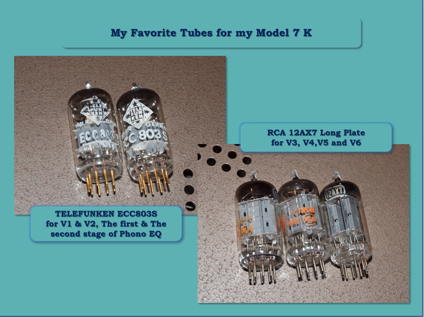
Now, for my modified Model 7 K, I reached the true clearness of sound of the sound stage by changing to the long plate RCA 12AX7. Especially in V3 and V6 where the cathode follower might need a powerful sounding tube.
In my hearing, the long plate RCA 12AX7 provides a bigger and deeper sound stage than any other tube, and a unique lively feeling that is so gorgeous and enjoyable!
The microphonic noise would be higher than Telefunken ECC83, but the tone amp's gain is around 10 dB to 20 dB, so the tube’s noise is not so critical as the phono EQ, and only the sound character of the tubes would be important factor, I believe.
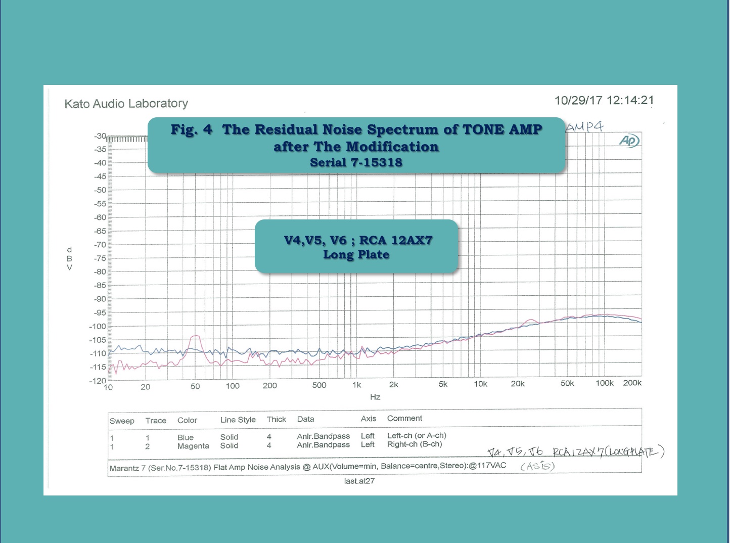
You can see the residual noise spectrum of the tone amp with the RCA 12AX7 for V4, V5, and V6 in Figure 4.
I suppose that under these conditions you can’t hear any noise from the speaker, but of course the noise might much depend on the power amplifier you are using.
I have long respected the RCA engineers, who firstly developed such a splendid 12AX7 in 1947 more than 70 years ago, only two years after the end of Second World War.
My Most Favorite Cartridge is the Shure V15 Type III with VN35MR Stylus
You might think I'm being quaint if I tell you that my favorite phono cartridge is an old MM type, the Shure V15 Type III.
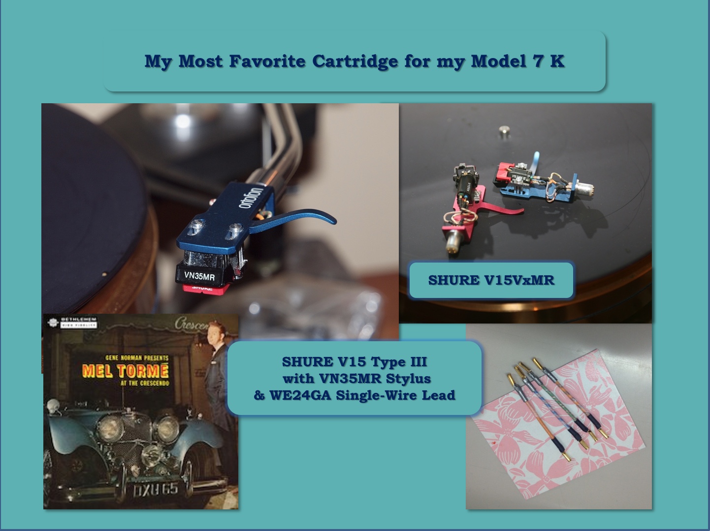
When I was a young engineer working at TEAC 45 years ago, I managed to get this cartridge. At that time the Shure V15 series had already built a reputation for its high quality sound in our Japanese market, and especially the Type III got the highest reviews.
But the day I fully recognized the true value of Type III was not so long ago, in 1997, when I come across the replacement stylus, VN35MR.
I was so surprised by its smooth and vivid sound that was fully free from distortion, and I was also impressed with the rich tone of its new Microridge stylus, especially in mid-high range.
Compared to Denon DL-103 I had long enjoyed, I felt the sound was so natural and the tone so supple. Furthermore, when listening to the live album Mel Tormé at the Crescendo, it sounded like he was present and singing just before me. Yes, the vocal through Type III + VN35MR was outstanding, and the harmony was much more attractive for me.
After five years I got the final version of the V15, the V15VxMR. This cartridge could reproduce well balanced and smooth tone throughout its entire range, but compared to the old Type III + VN35MR, it somewhat lacked its lively feeling.
In a word, the sound of Type III + VN35MR would be far more enjoyable for me, and the impression has turns to some kind of conviction of the superiority of Type III + VN35MR, coincided with the stages of version upgraded modification on my old Model 7 K.
About 10 years ago I found out about using the WE24GA head shell lead wires, which made the sound more real, just like the sound of WE16GA speaker cable did, as you might have already known well.
I don’t intend to insist that the Shure Type III + VN35MR is the best cartridge ever made, but I’d like to say this old cartridge can bring out the best potential of the famous “Marantz Circuit”, and allow us to truly and simply enjoy the superb musicality of Model 7.
What a blessing it is that you don’t need to install any step-up transformers or MC head-amplifier into between the cartridge and Model 7,
The Last Chapter
Well, first of all, I must express my sincere gratitude for Jeff-san, my kindred- sprit friend for giving me the chance to share simply my personal experiences throughout around 40 years to his eager readers, thank you very much!
Also, I’d like to dedicate my story to the true creators, Saul B Marantz, Sidney Smith, and the other unknown engineers that worked at Marantz at that time, who had created such a masterpiece in the Marantz Model 7.
I thank very much all of Jeff’s Place readers for going along with my long story, now up to Part 7. Of course, I want to give my special thanks for Handoko-san and Alan-san. They gave me the chances to modify their valuable original Model 7's. I have enjoyed the process of the modifications and it helped me understand a little bit of Model 7’s secrets.
In looking back upon my long adventure with Marantz Model 7 K, I am gaining a deep appreciation for the USA culture that produced such wonderful technology.
I have long loved American music and its sound, but I have also respected the high-technology developed there. For example, I have come across a lot of outstanding parts that I have introduced you to in these articles, from Part 1 to Part 7, and they are almost all "Made in the USA" parts. It is these great intellectual creations in the USA as a whole that has made the Marantz Model 7 one of the best products in audio history, I firmly believe.
If you had any personal inquiries for me, please feel free to contact me at [email protected].
And at last, I’d like to say thank you Kato-san for your support to complete my long adventure!
¸¸.•*¨*•♫♪¸¸.•*¨*•♫♪¸¸.•*¨*•♫♪
As always, every time I read one of Yazaki-san's articles I marvel at the wealth of knowledge and insight he has into audio performance, and how to improve sound & musicality to get that "Real Sound" we all crave.
In closing, it is a real privilege for me to be able to share Yazaki-san's Part 7 with you all, and I'd like to offer a huge "Thank you!" to Yazaki-san for taking the time to write up and share with us his experiences in modifying the vintage Marantz Model 7 preamplifier, one of the true masterpieces of audio history!
As always, thanks for stopping by, and may the tone be with you!