
It is always a pleasure to bring you posts from Yazaki-san for his article “My Adventure With My Old Marantz Model 7”.
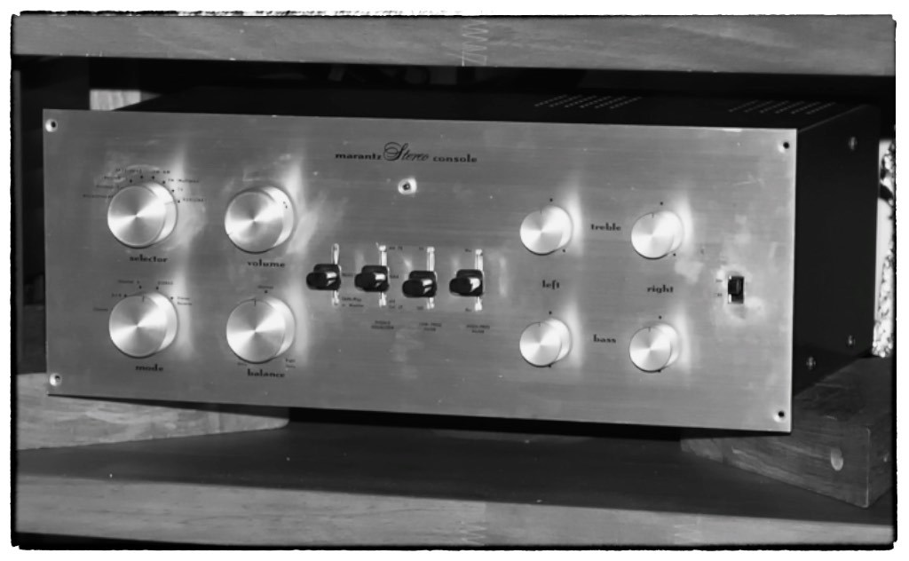
Yazaki-san's vintage Marantz 7k preamplifier.
Thank you, Yazaki-san, for taking time to write this article and share your substantial audio wisdom with us, it is very much appreciated by me, as well as all of us here at Jeff’s Place!
¸¸.•*¨*•♫♪¸¸.•*¨*•♫♪¸¸.•*¨*•♫♪
In Part 1 Yazaki-san told us about his near forty year passion of pursuing ‘real sound’ with his vintage Marantz Model 7 preamplifier, and the resulting enjoyment & satisfaction that pursuit has brought to his life.
Yazaki-san shared with us his thoughts about several brilliant design aspects of the Marantz Model 7, and how its design allows it to still hold its own against, or even surpass, anything made today in musical ‘real sound’ terms.
Yazaki-san also told us about his approach for fine-tuning the Model 7’s performance for ‘real sound’ through a careful selection of internal parts like capacitors and resistors, and finally, hinted at the modifications he was going to tell us about in Part 2 of his article that would take the Model 7’s performance to an even higher level.
¸¸.•*¨*•♫♪¸¸.•*¨*•♫♪¸¸.•*¨*•♫♪
In Part 2 Yazaki-san told us about his way of modification with his Marantz Model 7, and how important the quality of the power supply is to the overall performance, because the current from the power supply turns into the signal current.
Yazaki-san described for us how the switch to the Ultra-Fast & Soft Recovery STTH6112TV2 for +B rectification improved the speed of the current from the power supply, and lowered the noise.
Yazaki-san also described for us how he likes to install a hermetically sealed oil-filled capacitor into the subsequent stage of the rectifier tube or diode, connected in parallel with the main electrolytic capacitor for rectification, and how that its addition provides a more responsive and organic sound.
¸¸.•*¨*•♫♪¸¸.•*¨*•♫♪¸¸.•*¨*•♫♪
In Part 3 Yazaki-san told us about his discovery of how the addition of a decoupling capacitor for the +B voltage line (280 VDC for V3 and V6) of the cathode follower in the Marantz Model 7, brought about such an important improvement to the sound quality.
Yazaki-san also described how he brought out the full potential of π filters in his system by using Ohmite Brown Devil resistors in place of the original Allen Bradley resistors used in the Model 7, and shared with us his perceptions of how the inductance of various wattage ratings affected the overall tonality and voicing.
¸¸.•*¨*•♫♪¸¸.•*¨*•♫♪¸¸.•*¨*•♫♪
In Part 4 Yazaki-san told us how he learned about the use of mica capacitors in tube amplification circuits, more than 35 years ago now, in the MJ special edition book (1971) of Isamu Asano-san, “The Fascinating Tube Amplifier, Its History, Design and Assembly”.
Yazaki-san was impressed with the clarity and high-resolution of the high-frequencies with the NOS mica capacitors he tried, and how their mid-range had beautiful tone that was full of information, and how their overall sonic performance was full of exactness and elegance.
Yazaki-san attributed much of the excellent performance of these NOS mica capacitors them being fully free from inductance compared to any of the tubular style of capacitors.
Yazaki-san told us about when he installed NOS mica capacitors into his DA30 SET amplifier as coupling capacitors, the improvement in performance that resulted, and recommended we also try a mica coupling capacitor adventure of our own in our tube amplifiers to get a sense of what he experienced.
Yazaki-san told us about how his passion for the transparent performance of mica capacitors led him to develop and produce the Spec Corporation MC-DA series of ruby mica capacitors specifically for high-performance audio use in his own Spec products, and how Spec now also makes them available to the DIY community.
Yazaki-san went on to tell us about his use of the Spec ruby mica capacitors in his vintage Marantz Model 7 preamplifier as coupling capacitors, and they dramatically improved the sound quality, and brought out “an information rich sound” from his Model 7.
¸¸.•*¨*•♫♪¸¸.•*¨*•♫♪¸¸.•*¨*•♫♪
In Part 5 Yazaki-san continued to tell us about his adventure of working closely with Arizona Capacitors to develop the Red, Blue, Green Cactus capacitors, which he has developed over the last 7 years so that they are voiced to bring about optimum tone in several 'flavors'.
Yazaki-san shared with us valuable insights about how to distinguish the outside foil of any capacitor so it can be connected to ground for the lowest noise, and how he has marked each of the Red, Blue, and Green Arizona Capacitors so the outer foil is readily apparent.
Yazaki-san also shared with us a fascinating discussion about how Banno-san could very clearly hear how the choice of a capacitor’s raw materials affected the mechanical vibration and sound character of the dielectric or electrode of each capacitor, and how important the materials choice was to the overall tone of a capacitor.
Yazaki-san described how oil filled or impregnated capacitors tend to dampen vibration, giving superior tonal qualities, and that by combining various ratios of Kraft paper and film the the tonal qualities can be fine tuned to get the exact tone you want.
Yazaki-san then told us about upgrading the coupling capacitors in his vintage Marantz Model 7 preamplifier, and how he used the NASA developed wet tantalum capacitor as a cathode bypass capacitor.
¸¸.•*¨*•♫♪¸¸.•*¨*•♫♪¸¸.•*¨*•♫♪
Now let's read what Yazaki-san has to say in Part 6 of his article!
¸¸.•*¨*•♫♪¸¸.•*¨*•♫♪¸¸.•*¨*•♫♪
My Adventure with My Old Marantz Model 7K
Part 6: My Marantz Model 7K Resistor Adventure
Dedicated to Saul B Marantz and Sidney Smith for their true masterpiece!
By
Shirokazu Yazaki
The Ohmite WH Resistors I Met Recently
In Japanese, there is the word, Ne-Iro, that means tone or timbre in English. Ne means 'sound' and “Iro” means 'color'. By analogy Ne-Iro - or 'sound-color' - would be the color contrast character of lenses or films, as expressed in photographs or films. Richer contrast could bring us some kind of excitement when we see these pictures. A sharp and clear focus for the subject of is an important factor for creating impressive photographs, just as a clear-cut sound image is for creating Real-Sound, I suppose.
When I think of the sound of the Ohmite WH/WN resistor series, which came out just about 6 months ago, I am reminded of the very rich color contrast and sharp focus of my very old lens, a Contax Sonnar T* 85mm/f 2.8 made in West Germany by Zeiss.
The Ohmite WH/WN resistor was developed for industrial use, and is a newly developed molded wirewound resistor, with a very affordable price.
Surely, the usual wire wound resistor is not a resistor specialized for audio use, but in Ohmite's quest to develop an extreme characteristic resistor they have achieved an incredible quality resistor in the WH/WN that can also be used in audio products.
Basically, I have experienced that a wire wound resistor with a lower watt rating is the more desirable sounding than one with a higher watt rating.
I have felt that the 8W Ohmite Brown Devil was the one goal of my resistor adventure because of its most desirable rich and clear tonal character of the mid and mid-low range. Its color contrast is so clear and deep, so it could bring us so impressive feelings.
The Ohmite WH 5W 10-Ohm resistor has that desirable character of the 8W Brown Devil 10-Ohm. The Ohmite WH 5W resistor has a very information rich sound throughout its entire range, and the energy balance might be perfect for my hearing, and it has that preferable character of the wire-wound resistor in being lively feeling.
The Ohmite WN is a non-inductive type, but I prefer the usual wire-wound type, the Ohmite WH, as the WN can sound unnatural because it has too high of resolution in the high-end.
I have experienced a lot of times when modifying my tube power amplifiers that how a cathode resister’s quality and character have an enormous effect on the final quality of sound, as the signal current itself flows from the cathode to the ground through this resistor.
Actually, I was strongly impressed by the improvement in sound quality after changing the cathode resistor of my Western Electric 310A mesh tube, which is the driver tube for the DA30 in my SET amp, to this WH 1K Ohm.
When I put in the WH 1K Ohm resistor in my SET it was just like the dynamic range and the sound stage were extended. In a word, the sound changed to being closer to Real-Sound. I was so encouraged with the results, and so I started to think and study seriously how to apply the WH resistor to the modification of my old Model 7K.
This was a most recent development, of only a few months ago.
How To Use the Ohmite WH Modification of the Marantz Model 7
So, I looked anew at the parts list of the service manual for the Marantz Model 7, and I found out that different types of resistors were specified for each cathode resistor for the first stage tube and the second stage tube of preamp (phono EQ V1-A&B, V2-A&B), and also for the tone amp (for the high level input, V4-A&B, V5-A&B).
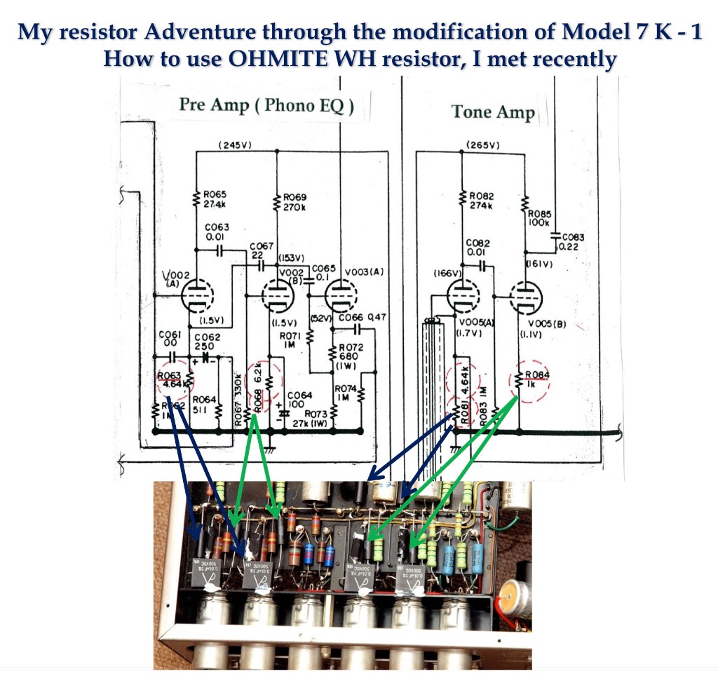
For the cathode resistors of the first stage tube, R63 A&B and R81 A&B, 2% deposited carbon resistors were specified, and for the cathode resistor of the second stage tube, R68 A&B and R84 A&B, 10% carbon composition resistors were specified.
One more thing I noticed was that the plate load resistors for the first stage, R65 A&B and R82 A&B, were 5% deposited carbon resistors, and also the resistors for the second stage, R69 A&B and R85 A&B, were specified as 10% carbon composition resistors.
With intention, the engineers at Marantz selected deposited carbon resistors for the cathode resistor and the plate load resistor of the first stage tube.
The first stage cathode resistor would mainly decide the gain, so the 2% accuracy resistor might have been selected for that reason, but the transmitted signal information through the first stage tube is surely very critical, so the deposited carbon resistor might have been selected not only for the accuracy, but also for its sound character or quality, I guess.
Once something is lost from the signal information at the first stage, it should be impossible to recover it in the latter stages, but the sound character could be compensated.
Compared to the numbers of pieces used of Allen Bradley carbon composition resistors, the number of deposited carbon resistors is small, up to only five pieces for one channel, but it would be true that the combination of Allen Bradley carbon composition resistors with deposited carbon resistors could have surely achieved the famed Model 7’s sound quality.
There are different views about the Allen Bradley carbon composition resistors, I understand, but the most negative point of the Allen Bradley resistor might be the dull or not so clear sound, which by analogy is like an out-of-focus picture, especially at the lower value resistances, up to around 10K Ohm, in my experience.
The Allen Bradley resistor has a lot of good attributes, such as a non-inductive structure, absolute reliability, not cutting down the resistive element, and also it is available in a wide range of resistance values.
Furthermore, the Allen Bradley's deep and rich mid-to-low range could bring us comfortable and old familiar feelings, but in my opinion, it has a warm sound but is kind of dull, which might come from the higher noise level of its characteristic.
Anyways, the deposited carbon resistors of the first stage tube, for both the cathode and the plate load, might have added another type of preferable sound character to Allen Bradley resistors, I suppose.
One more thing, is that for the Allen Bradley resistors the resistance value can drift to higher values over its 10% tolerance rating over a long time in use in some environments, and actually, I experienced that when I restored and modified Hondoko-san’s original Model 7. The higher value would decrease the current for that circuitry, and it might be safer way, but the frequency response of the filter circuitry would lead to inaccuracy compared to the originally specified response.
With that as background, we could assume that the innovative Ohmite WH resistor could improve the sound quality of the preamp phono EQ, and the tone amp, of the Model 7.
Only a few months ago, I wanted to realize the true potential of the Ohmite WH resistor, and tried changing the resistors in my Model 7 to WH 5W 5K Ohm and 1K Ohm for the cathode resistors of the first stage, and also the second stage, R63; 4.64K Ohm, R68; 6.2K Ohm, R81; 4.64K Ohm and R84; 1K Ohm.
The value of the WH 5K Ohm is surely different from specified value in the circuit diagram of Model 7, so I asked for Kato-san’s advice. Kato-san is an old friend of mine, and is an authority about the circuit technology of tube amplifiers.
Kato-san said that changing to the WH 5K ohm for R63 A&B and R64 A&B would essentially be no problem, because the differences are within an acceptable 10%, but about R68; 6.2K Ohm, in Morikawa-san’s MJ article “How to Build Up the Model 7K Kit”, he had checked five sets of original Model 7 with varied serial numbers, and he found out early Model 7 production serial numbers had adopted 4.7K Ohm resistors instead of 6.2K Ohm resistors for R68.
Actually, according to “Service Manual 7C”, the 4.7K Ohm resistor is described in the attached circuit diagram, but curiously enough, the 6.2K Ohm resistor is listed in the parts list.
Morikawa-san thought that since R68 is only a self-bias resistor, whether it was a 4.7K Ohm or a 6.2K Ohm resistor would not matter, but he supposed that the sound of a 4.7K Ohm resistor would be more vivid, so he decided to use a 4.7K Ohm resistor for his Model 7K, as he described.
So, given that, I decided to install the Ohmite WH 5W 5K Ohm resistor also R68, as it was close to the value of Morikawa-san's choice of the 4.7K Ohm resistor for his Model 7K.
The results of this modification surely brought me very intense impressions, and that generally the resistors' contribution as a percentage of the parts reaches to quite a higher level, even compared to the capacitors', I suppose.
With the rapid pace of technological development, thankfully I met the outstanding Ohmite WH resistor in the literature, and the Ohmite WH resistor could have the ability to change our past common sense of audio resistors, and it could bring us true “Real-Sound” with perfect musicality, I simply believe now.
About the plate load resistor, I’m now trying now, and so I could report on it in near future.
The Tepro Type RA as Phono Input Resistor
Just like the cathode resistor for the first stage tube, the phono input resistor has enormous effects on the signal voltage transmitted to latter stages, and of course to the final sound quality of the phono EQ, because the very slight signal current from the cartridge is changed to the signal voltage when connected to the grid of the first stage tube.
For the Model 7, R1 A&B or R2 A&B, are the input resistors, and the specified values for each are 47K Ohm is specified. I strongly recommend you change R2 (phono input two) to a Tepro RA 1W 47K Ohm resistor so you could make a hearing comparison between phono input one with the original Allen Bradley carbon composition 1W resistor.
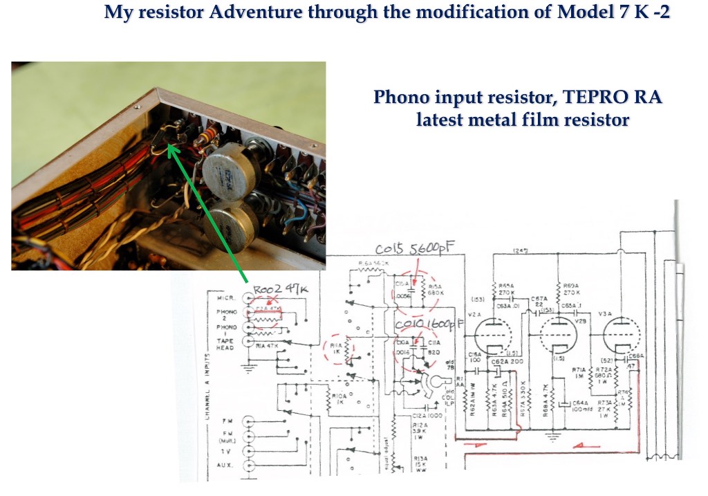
The Tepro RA was developed for audio use a few years ago, and is the latest type of metal film resistor. The noise level is exceptionally low, so the sound is so fine and clear for my hearing, and the energy balance from the high-end to the bottom-low-range is almost flat, with beautiful timbre.
In a word, the sound character of Tepro RA would be quite modern, with highest resolution, and the sound image could be brought to good focus. If I could tell my taste, I love the sound of Tepro RA’s as phono input resistors, and I feel the resistor could bring out well the full musicality and sound potential of my very old Shure V15 type 3 + VN35MR (Micro Ridge stylus), with the phono EQ of my Model 7K.
If you find a splendid sounding 47K Ohm for your hearing, you could easily do a resistor adventure by changing the Allen Bradley R2 installed at the RCA jack on the rear panel and comparing them.
The Change of Output Level Potentiometer to Fixed Resistors
In the Marantz Model 7 an output level potentiometer R54 A&B is installed in the rear panel. It works to tailor the output level of the Model 7 to match the power amplifier’s gain, and once we adjust the pot, we don’t need to use it often.
So my recommendation is to change the R54 potentiometer to fixed resistor. If we change the potentiometer to a usual fixed resistor, the long-term reliability could improve, the accuracy of channel balance could be improved, but furthermore, we could select the most desirable sounding fixed resistor, so we could surely get an improvement to the sound quality.

In the case of the Marantz 7 output level potentiometer, the total gain of my tone amp is 12.5 dB, according to Kato-san’s recent accurate measurement, and this gain level has been fitted to my system, consisting of two power amplifiers and my high sensitivity Altec 414A plus Onken 500MT (mid) plus Onken 5000T Esprit (tweeter) speaker system.
The maximum gain of the tone amp is 24.5 dB, and just 12 dB turns the level down from the max output gain.
So I changed the R54 A&B 500K Ohm potentiometer to a 500K Ohm Caddock thick metal film resistor for each channel. It’s my opinion that thick film resistors are basically well-balanced and pliable sounding, and they could be promising for audio use in the future.
For the original Model 7’s tone amp the maximum output gain is specified at about 22 dB, which is 2.5 dB lower than Model 7K. The difference is due to the type of channel balance volume control on the front panel.
The type MN volume control was adopted for the Model 7K, and the type AC volume was used in the original Model 7. The benefit of the MN volume control is that there is no loss at the center position of the balance volume, but the AC volume control at the center loses around 2.5 dB, so the MN volume control would be a desirable factor for the sound quality of Model 7K compared to the original Model 7.
Anyways, changing the R54 A&B output level potentiometer for an original Model 7 has to be adjusted for that difference, so for example, going from 300K Ohm pot to a fixed resistor with same resistance, and so an original R53 A&B 180K Ohm fixed resistor should be changed to 380K Ohm (180 K ohm + 500 K ohm – 300 K ohm ) fixed resistor.
Changing to these fixed resistors could realize around 15 dB gain for the original Model 7’s tone amp.
The changing to fixed resistors, as I mentioned, would be very preferable both for being fully free from noise, for long term reliability compared to using a potentiometer, the accuracy of channel balance, and furthermore an improvement to sound quality.
A high quality resistor like the Tepro RA metal film resistor, with its accurate sound, would be desirable, I suppose.
Well, I have traveled so long, but I’m still on my way in a 'resistor adventure', and I am thankful I came across the finest quality resistors for signal circuit use, such as the innovative Ohmite WH and Tepro RA, that I can share with the readers of Jeff’s Place.
Well, thank you very much for your going along with me to this point, Part 6!
To be continued.
¸¸.•*¨*•♫♪¸¸.•*¨*•♫♪¸¸.•*¨*•♫♪
Another big thank you to Yazaki-san for his fascinating discussion about his resistor adventure with his vintage Marantz Model 7k preamplifier, it is both intriguing and enlightening!
As always, thanks for stopping by, and may the tone be with you!