

It is my great pleasure to bring you the third post for the article that Yazaki-san is writing for us, “My Adventure With My Old Marantz Model 7”.
Many thanks to Yazaki-san for taking time to write this article and share his wisdom with us, it is very much appreciated by me, as well as all of us here at Jeff's Place!
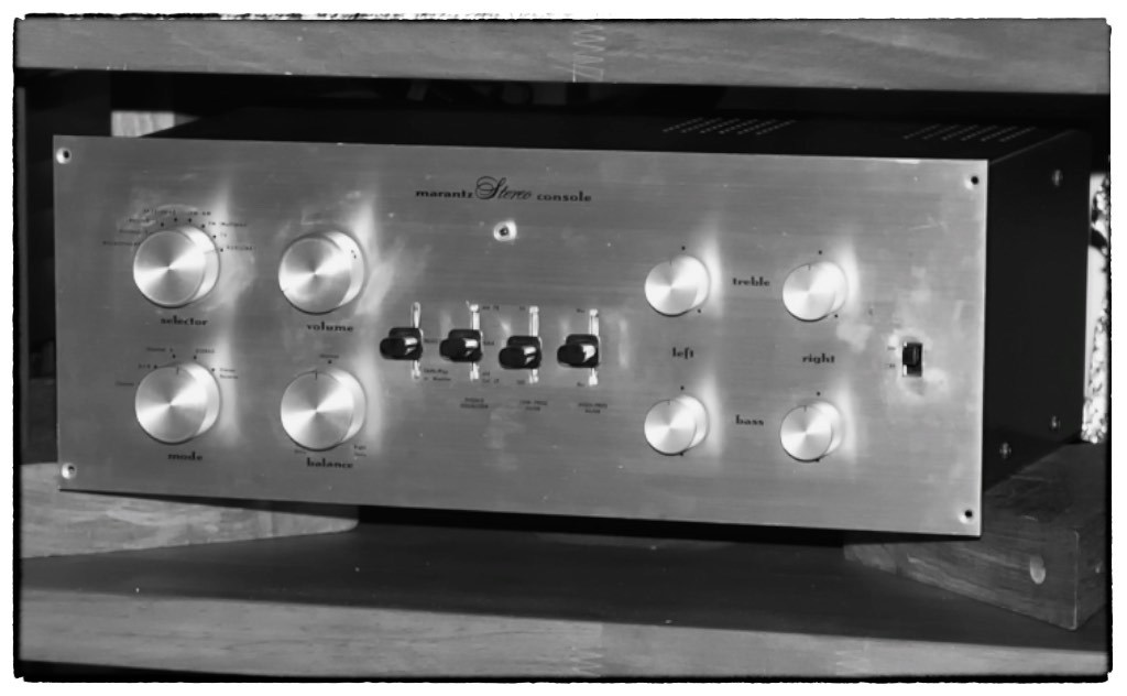
Yazaki-san's vintage Marantz 7k preamplifier.
In Part 1 Yazaki-san told us about his near forty year passion of pursuing ‘real sound’ with his vintage Marantz Model 7 preamplifier, and the resulting enjoyment & satisfaction that pursuit has brought to his life.
Yazaki-san shared with us his thoughts about several brilliant design aspects of the Marantz Model 7, and how its design allows it to still hold its own against, or even surpass, anything made today in musical ‘real sound’ terms.
Yazaki-san also told us about his approach for fine-tuning the Model 7's performance for ‘real sound’ through a careful selection of internal parts like capacitors and resistors, and finally, hinted at the modifications he was going to tell us about in Part 2 of his article that would take the Model 7’s performance to an even higher level.

In Part 2 Yazaki-san told us about his way of modification with his Marantz Model 7, and how important the quality of the power supply is to the overall performance, because the current from the power supply turns into the signal current.
Yazaki-san described for us how the switch to the Ultra-Fast & Soft Recovery STTH6112TV2 for +B rectification improved the speed of the current from the power supply, and lowered the noise.
Yazaki-san also described for us how he likes to install a hermetically sealed oil-filled capacitor into the subsequent stage of the rectifier tube or diode, connected in parallel with the main electrolytic capacitor for rectification, and how that its addition provides a more responsive and organic sound.
Now, without further ado, here’s Part 3 of Yazaki-san’s article about his life with the Marantz Model 7k – enjoy!
¸¸.•*¨*•♫♪¸¸.•*¨*•♫♪¸¸.•*¨*•♫♪
My Adventure with My Old Marantz Model 7k
Part 3: My Way of Modification
Dedicated to Saul B Marantz and Sidney Smith for their true masterpiece!
By
Shirokazu Yazaki
Addition of Decoupling for Cathode Follower
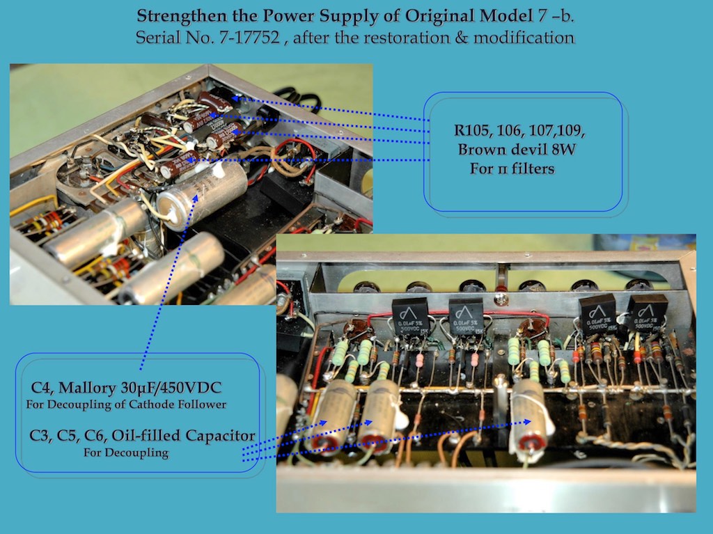
I happened to experience a surprise just one year ago when I completed the restoration and modification of Handoko-san’s original Model 7, when I made the addition of a decoupling capacitor for the +B voltage line (280 VDC for V3 and V6) of the cathode follower, which brought out an extremely massive and deep sound.
Surely, I wanted to realize the same type of sound with my Model 7 k, and I started to search for the reasons of that result.
At last, I reached the conclusion that the one major difference of the modifications between my Model 7k and Handoko-san’s original Model 7 that I restored & modified, was the addition of the decoupling capacitor for the cathode follower.
Actually, I added my favorite Mallory 30μF/450VDC ( C4 ) just before the 280 VDC line for the cathode follower tubes, and was able to experience the same renewed sound with remarkable forcefulness also through Model 7 k, which I had never heard before.
Please look at the figure, “Comparison of Tube Preamplifiers” by Kato-san and “Tube type” in it.
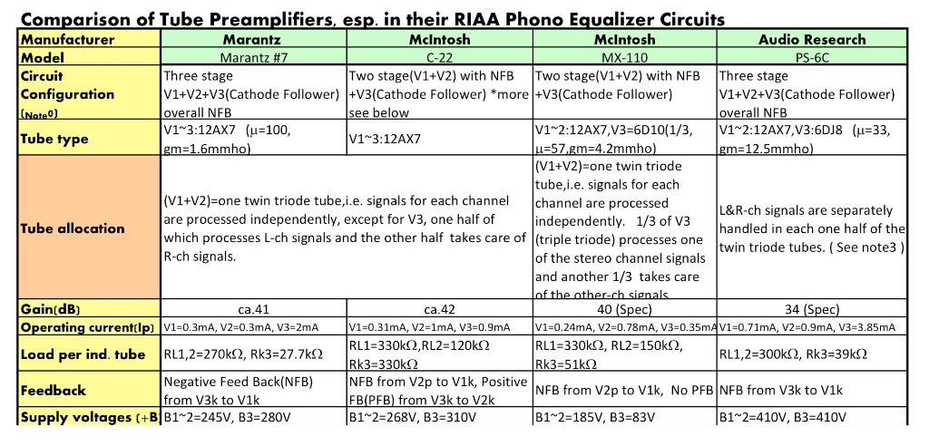
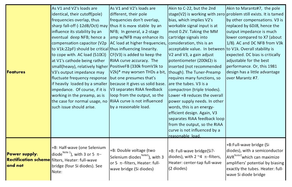
You can see the tube types of phono EQ circuit for each preamplifier, Marantz Model 7, McIntosh C22, MX-110, and Audio Research PS-6C, consists of exactly the same tube, the 12AX7 (ECC83) for V1 & V2, but the Model 7 and C22 use a 12AX7 for V3 as the cathode follower.
However, the MX-110 was designed to use the 6D10 for V3, and a 6DJ8 was adopted in the PS-6C at V3, to use as the cathode follower.
The values that express the amplification degree of these tubes are, for the 12AX7; μ=100, the 6D10; μ=57, and the 6DJ8; μ=33.
Therefore it could be easily understandable that 12AX7 has the highest gain of these tubes, and it apparently fits well for the phono EQ circuit, which requires a high gain tube, but would it also be a good fit to use as a cathode follower?
I understand well that the cathode follower circuit is designed for reducing the output impedance, and the lower output impedance of a preamplifier would be desirable.
The relation with the output impedance and the input impedance of the power amplifier would be a relative matter, and because the usual tube power amplifier’s input impedance would be higher than 100k ohm, that the Model 7’s output impedance could be sufficiently low level, and so practically we could see no problem about the design of Model 7, I suppose.
Meanwhile, Kato-san described with his words how in the PS-6C that V3 is replaced by a 6DJ8 tube, and as a result the output impedance is much lower compared to a 12AX7.
Generally speaking, the lower output impedance tubes would be better for driving later tubes forcefully, and I agree with that. In such a point of view, the sensitive tube, 12AX7 would not to be the best tube for using as the cathode follower circuit, and so the engineers at Audio Research obviously made a decision to use a 6DJ8 instead of 12AX7 for V3.
Also, according to one popular theory in Japan, because the 12AX7 is not a powerful tube, and furthermore, because of its higher impedance, using a 12AX7 as a cathode follower is questionable, I have often heard.
But I have found that such a concern for 12AX7 was proved unfounded through the results of Handoko-san’s Model 7’s modification.
Yes, 12AX7 transformed itself to be like a more powerful tube! Can you imagine?
I found out the fact that when we need more forceful sound through the cathode follower circuit, installing a little bit excessive value capacitor for the decoupling of the local power supply accomplishes this quite well.
I also installed oil-filled capacitors by Arizona Capacitors into + B, 245 VDC line for V1, V2 ( C6 ), and also +B 265VDC line for V4, V5 ( C5 ).
These additions of decoupling capacitors bring out more sensitive, but also stable sound, from Handoko-san’s Model 7, and also my old Model 7 k.
How to Bring Out the Potential of π Filters
Please take a look at the circuit diagram for the modifications below.
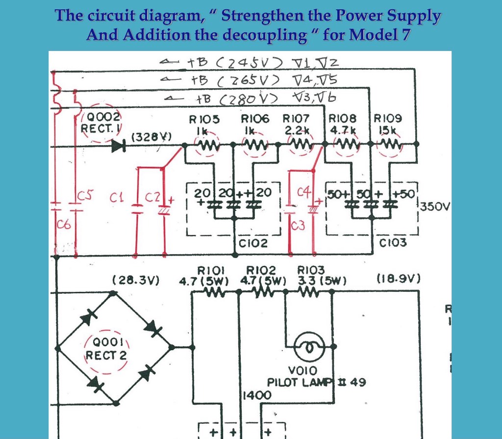
You can see 3 π filters before the +B, 280 VDC line, for the cathode follower, V3 and V6 tubes, and a total of 5 π filters are installed before 245 VDC line, for V1 and V2 tubes, for the phono EQ.
Basically, a π filter consists of a pair of capacitors and an inductor for reducing the noise and/or ripple from the rectification (mainly), and it works well under the condition of comparatively stable current flowing into the load through this relatively simple circuit.
But in the Model 7, 1/2W Allen Bradley carbon composition resistors are used for R105, 106, 107, 108, and 109, instead of using an inductor.
I have had a question for long time, why the designer adopted the carbon composition resistors for π filters, because the one major merit of carbon composition resistors is that they are fully free from inductance.
Of course, the current is only about 10 mA, so that a definite amount of inductance would not be needed, I suppose.
Well, it was just three years ago now, that I found the resistor that I had long searched for.
At that time, I longed to have an exceptional sounding resistor for improving the sound of our Class-D amplifier. I had already narrowed the target to a wire-wound resistor, when I came across the Ohmite 200 series, the enamel coated Brown Devil.
I used this type of resistor when I built up the monaural DA30 SET's for my friend Ookubo-san, 5 years ago now.
I recalled the sturdily-built sound of Ookubo-san's SET's at that time, and I did trials with the Ohmite Brown Devil resistor for our SPEC products. The result was beyond my imagination!
I made a hearing comparison of Brown Devil resistors for with values of 20W, 12W, 8W, and 5.25W, and they all had in common such rich timbre in the mid-to-low range, and I was impressed with the sturdily-built sound, just as I remembered from Ookubo-san’s monaural SET's before.
The tonal balance was different for each one. The 20W Brown Devil had a very heavy tone, and 5.25W Brown Devil’s tonal character stood out in the mid-to-high range. I got the most desirable impressions from the 8W and 12W Brown Devil's as well.
Well, when I measured the inductance value of of each Brown Devil, I understand the reason why.
The inductance value of 20W Brown Devil was the highest, and 5.25W Brown Devil had the lowest inductance value.
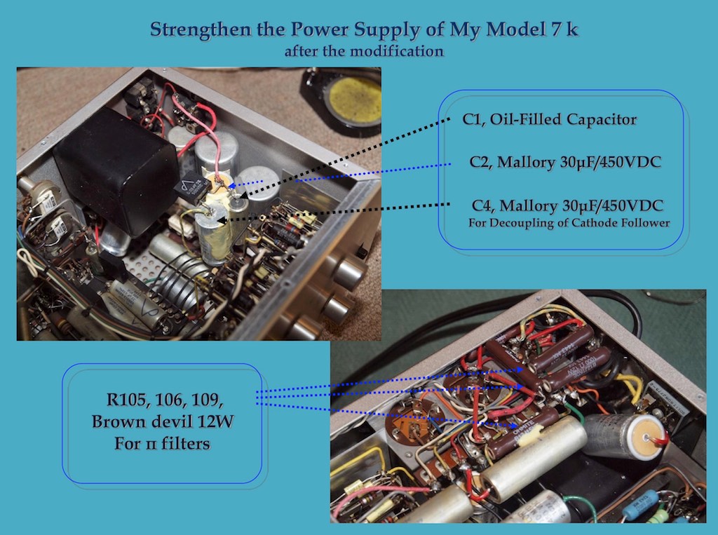
Anyway, I recognized the Brown Devil has some degree inductance, and I decided to change the Allen Bradley carbon composition resistors to Brown Devil wirewound resistors for R105, 106 and 109 of my Model 7 k.
But I could not get a 12W 2.2k Ohm Brown Devil for R107, or a 4.7K Ohm Brown Devil for R108, so I selected an Ohmite 20 type wire-wound resistor with an enamel coating, instead of the Brown Devil's.
The results turned out marvelous enough, and I have enjoyed the clear but powerful sound with my Model 7 k after making the change.
For Handoko-san’s original Model 7, I used mainly Brown Devil 8W resistors because the 12W version is big and long, and makes installation too difficult.
The Brown Devil is a primitive, simple, and very old type of resistor, and has some inductance value, and so in a very real sense, the Brown Devil should be far from the ideal resistor.
But for some analog circuits, in which flows some amount of current, especially as a plate resistor for a driver tube, or a cathode resistor for a power tube, in a self-bias circuit, the Brown Devil can work very well because of its high reliability, and it brings out very real and musical sound, I have experienced.
I suppose that the inductive aspect of the Brown Devil rejects or does not transmit the harsh part of the spectrum in the current.
So I would like to highly recommend that you try the Brown Devil's not only in your Model 7, but also in your favorite tube power amplifier.
Well, my way of the modification for power supply will come to a close for now.
It might seem complicated for you to try all the modifications I have written about at one time, but you could start first with just changing the rectifier to STTH6112, and installing the oil-filled capacitor for C1, and through these modifications, you could get a feel for how a modified Marantz Model 7 is such a "real" music reproducer even today.
To be continued.
¸¸.•*¨*•♫♪¸¸.•*¨*•♫♪¸¸.•*¨*•♫♪
Many thanks to Yazaki-san for sharing his life with the Marantz Model 7 with us!
There’s a lot to think about and absorb from what Yazaki-san has said in Part 3, just as in Part 2.
I’m in the process of digesting it all, while at the same time contemplating some adventures based on his recommendations!
I’m already looking forward to reading the next part of Yazaki-san’s article My Adventure with My Old Marantz Model 7k, and as Yazaki-san is known to say, please wait for it!
As always, thanks for stopping by, and may the tone be with you!