
The Encounter with NOS IRC Metal Film Resistors in the 60s
I used to have a long professional life as an engineer and a manager of engineering division. Certainly, it had been desirable to intelligently study, judge and process things. However, when it comes to my hobby life, looking for “Real-Sound”, I think I've left myself to something rather more intuitive.
Through the process of modifying these Model 7s, Alan-san’s and Roy-san’s, as described above, I came up with this idea about resistors with high resistance values that is inevitable for vacuum tube amplifiers.
Yes, I realized now it was time to focus on and look out for such NOS metal film resistors, which boast reliability, accurate values, and above all its transparent sound image reproducibility that allows us to see behind.
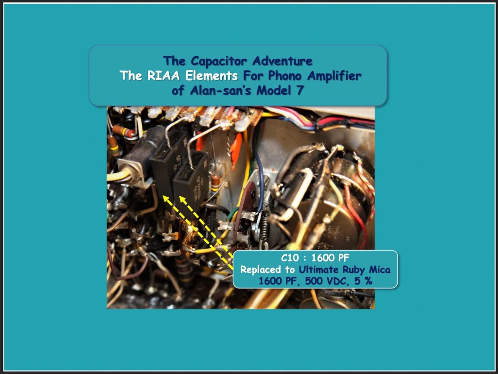
On the other hand, in the summer of 2019, my long “Capacitor Adventure” also came to an end with the encounter with Ultimate Ruby Mica capacitor. This was explained in detail in Part 9, but the best sound quality of this mica capacitor is, in a sense, non-individuality. It effectively dumps the vibration of the dielectric and electrodes, minimizes the loss coefficient, and approximates an ideal capacitor, resulting in colorless and transparent sound quality.
That is, the transmitted signal through these mica capacitors is not colored. So, even if multiples of these mica capacitors are connected in parallel, the E.S.R. will surely decrease and so the transparency of the sound will only increase, but it is completely unrelated to the slight sense of density in the mid-high range, and a little bit of a glossy tonal character peculiar to the usual mica capacitor.
So even in resistor, again, I intuitively decided that this type of old NOS, relatively large-capacity metal film resistor was the one that would match the sound quality of the Ultimate Ruby Mica capacitor.
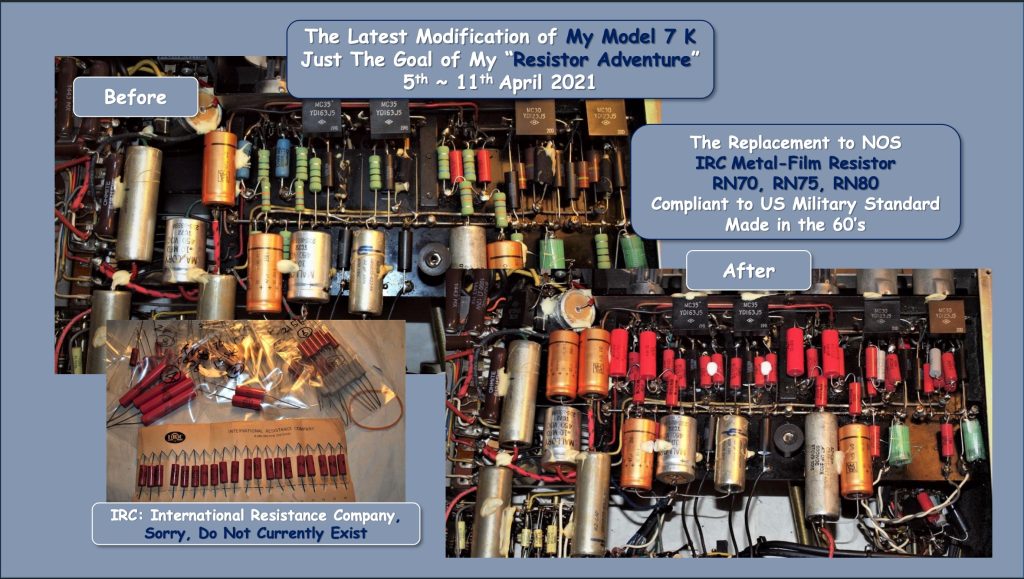
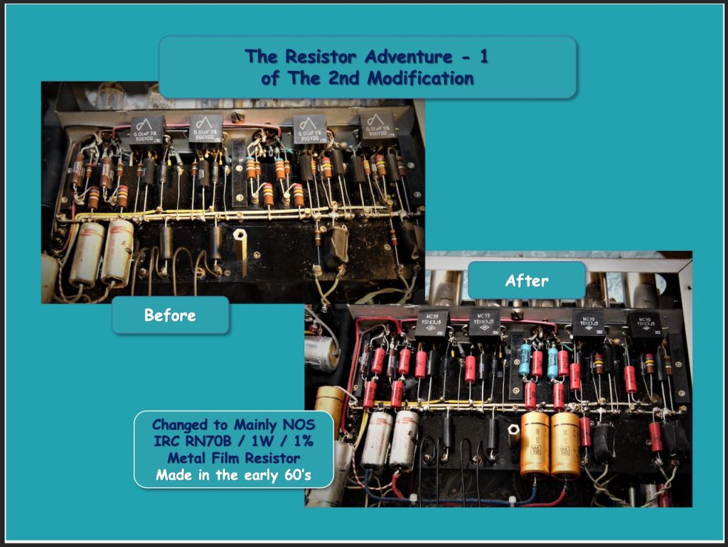
Finally, we, Kajiwara-san and I, came across IRC metal film resistors, RN70 (1W), RN75 (2W), RN80 (3W), which were produced in the 1960s.
As you can see from the model number, it was a quality-controlled resistor by US Military Standard, which was exactly developed for US aerospace applications. Thankfully, I became acquainted with the NOS parts shop in Japan, which stocks a large number of these rare resistors. I'm sorry that the company, IRC, doesn't seem to exist now.
Even so, what a beautiful appearance these resistors have! Strangely, I think that resistors and capacitors with a structure sealed with such a thermosetting resin generally have excellent sound quality.
For example, in the case of resistors, the current Ohmite WHE is, and for capacitors, the former Sprague Bumble-Bee, Black Beauty, and CDE's Black Cat, Good All, would be the examples.
The best thing of the metal film resistors might be the resistance value with high accuracy of 1% or less.
I've modified two Model 7 originals and three Model 7 Replicas so far, but what always made me feel gloomy is the inaccuracy of the resistance values of solid carbon resistors, including Allen Bradley. It is true that the allowable resistance value of solid carbon resistor is usually ± 10%, but about + 15% is commonly seen, and by all means, it might have been changed significantly from the original condition.
Certainly, the resistance of a little out of the allowable value could be acceptable when the resistor is used in fixing the operating point of the tube, but it is never desirable for the resistor that determines the gain and the cutoff frequency in the signal current flows directly in the voltage fixing.
The differences of the left and right channels of these resistance values not only brings about a level difference, but also brings about the difference of the frequency response characteristic and the phase characteristic.
Well, I have felt that one of the joys of stereo playback and truly stereophonic sound would be that it can put you in a sound field that spreads not only from the left to the right, but also the depth, from the front and the back, in detail, as if I were at the recording site of the music, and rather I could place clearly the location of the performer, the vocalist and the instrument.
I realize that in order to enable the stereophonic image, which is made of rich sound field information and sharp sound image, not only the frequency response characteristic but also phase characteristic of each left and right channel needs to be nearly the same.
Not only from the viewpoint of pursuing sound quality, but in this sense, I’d like to rather emphasize that it is extremely important to use a highly accurate ± 1% resistor in the signal circuit. Also, as will be described later, this is demonstrated in the impressions of my friends, who experienced the sound of Model 7’s 2nd modification version with mainly featuring this IRC metal film resistors made in the 1960s.
A Consideration on Resistors
As you know, the passive elements that make up a circuit include resistors, capacitors, and inductors. It can be said that the element which has the closest ideal characteristic among these three is the resistors.
On the other hand, the physical evaluation criteria related to the sound quality of capacitors include the frequency characteristics of impedance, E.S.R (Equivalent Series Resistance), and Tan δ, dissipation factor.
By looking at these measured values, various types of capacitors, for example, the differences between electrolytic capacitors, tubular type capacitors, and also mica capacitors can be seen very clearly, and in some cases, even significant differences in the individual sound quality among each type can be read.
This means that what constitutes a capacitor is not only the capacitance of component, but also the resistance component, and the inductance component cannot be ignored.
In other words, there is never any pure and genuine capacitor in this world. However, in the case of a resistor, it deals with a relatively simple physical phenomenon in which the current flowing through the resistor is simply consumed and converted into thermal energy, and there would be no room for the capacitance value or inductance component to enter.
Therefore, with regard to resistors, the voltage drop, which is its function, does not depend on the frequency, and at least the differences of static characteristics in individual resistors would be far smaller compared to capacitors.
Of course, the large wattage enamel wire-wound resistor, which is often used for the cathode resistor of power tube and the power supplies, and has constitutionally a certain inductance component, but on the contrary, it also has some merits in sound quality, and anyways it can be said that this case is an exception.
That is, when considering the resistors, only the energy conversion from the electric energy to the thermal energy by the resistor needs to be considered. In the process of conversion to this heat energy, the very low level noise that would be directly related to the sound quality is generated.
Now, I’d like to introduce you the descriptive text about the resistor noise from KOA Corporation’s web-site, a major resistor manufacturer in Japan. They explained in the chapter, “Low Current Noise" that “Noise of resistors are categorized into “thermal noise” or “current noise”. Thermal noise is logically determined by resistance value, absolute temperature and frequency bandwidth, and has no relation with the resistor material. In addition, the effective value in unit interval of frequency is extremely small and distributed uniformly in the frequency domain, which leads to the main factor of deterioration of the S/N in broad band amplifier of wireless frequency. However, it doesn't normally pose any problems in the frequency range below the audio frequency. On the other hand, current noise largely depend on the material, and becomes larger as the frequency lowers. In the frequency band below K Hz, the effective value in unit interval of frequency is larger than the thermal noise; it increases incomparably especially in the frequency band below a few Hz. For this reason, current noise is the main cause of S/N degradation, rather than thermal noise, in applications that handle low voltage near direct current, such as photo detector circuits (shown in the figure below) and electrocardiographs that amplify small detection signals with a large gain. In such applications, metal film resistors with low current noise, such as RN73R, RN73H, MF, RNS, and MRS are suitable.”
Up until now, when it comes to resistor noise, I've only understood the physical term as thermal noise. However, I realized that the concept of the current noise is more effective in qualitatively understanding the difference in sound quality of various resistors as I have described so far.
Now, based on the above the definition of thermal noise and my experiences, I would like to specifically describe the selection or usage of resistors to suppress noise generation due to resistors as much as possible and obtain high sound quality.
First, from the theorem that thermal noise is proportional to absolute temperature, the principle that a resistor with as large a power capacity as possible should be used holds. This really fits my experience, for example, even with Allen Bradley's solid carbon resistors, the 2W large ones are much clearer and richer in information than the 1W ones.
One of the reasons for this is that the large resistor has a larger heat dissipation area and the temperature does not rise sharply. The setting of the wattage capacity of a resistor is naturally calculated by multiplying the voltage value to be dropped and the current to flow through the resistor.
However, from the point of view of sound quality, I would like to recommend you to use a resistor of the largest size possible to be installed without sticking to this equation. Rather, for us, maximizing sound quality is the first priority, and it should be free from cost pursuits such as product design made by manufacturers.
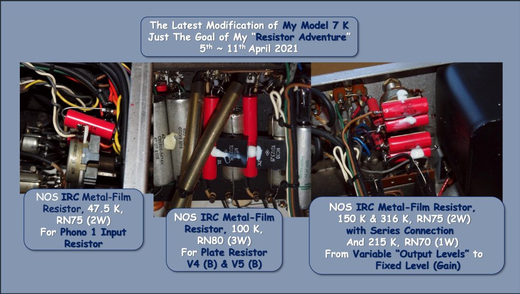
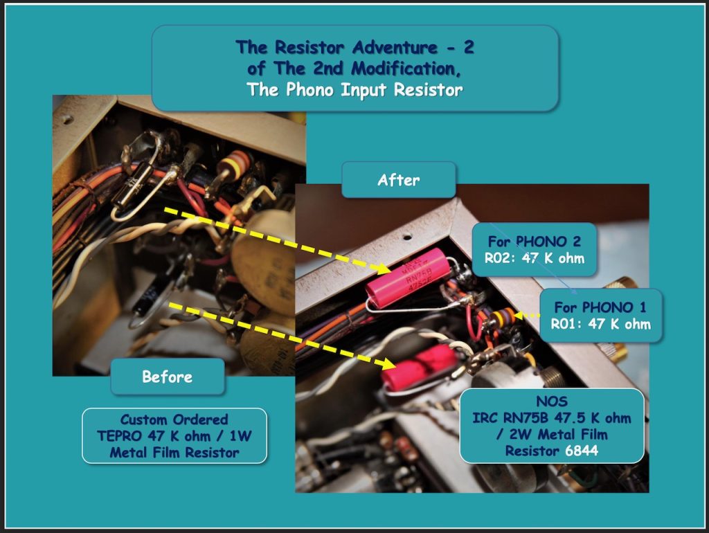
Well, in Alan's 2nd modification of Model 7, one example in which this principle was clearly shown was the input resistor of the Phono EQ, R01 or R02, 47 K ohm.
This resistor also has the role of receiving an insensible current from the cartridge and generating a minute voltage across this resistor, and the upper limit of the voltage here and the noise generated in this resistor exactly determine the dynamic range of the input signal.
To emphasize the point with a little exaggeration, this single resistor is truly a key-component that determines sound quality of reproducing an analog LP, which would be more important than any types of RIAA circuits or the components used.
In Alan-san’s and Roy-san’s first modification, I was aware of the importance of this resistor, I replaced with the custom-ordered TEPRO metal film resistor, 1W to the original solid carbon resistor only in the Phono 2 input, R02, and so, it was very easy to compare with the sound quality of Phono 1, originally installed solid carbon resistor.
The difference was so clear that anyone could point it out, I suppose. When I listened to the sound of TEPRO 1W, the sound of a solid carbon resistor could only be said to be “low-fidelity” in comparison.
Well, what I prepared for the 2nd modification this time was the IRC, RN70 (2W). I have never felt or experienced such a quiet silence in the sound of analog LP. Although it is an image of this sound, but the tone with the highest transparency and full of density just springs forth from the true silence stereoscopically, and that also it spreads up instantly.
Well, I think of the incredible appeal of the sound reproduced by Shure V15 Type 3 cartridge + VN35MR stylus. I already shared with you in Part 7 about the wonderful compatibility between Model 7 and this cartridge body and stylus, but at that time, I avoided declaring this old Shure as the supreme cartridge, but I would like to make it clear now that there is no other cartridge like this Shure with the richest musicality after this 2nd modification.
If this phono EQ had such a highest degree of perfection with the combination with the MM cartridge, I can’t help but think that there couldn’t have been a general evaluation or reputation of the superiority of MC cartridges over MM cartridges.
Certainly, in semiconductor preamplifiers, which became mainstream in later years, the upper limit of the allowable input level was crucially limited, and it seems that the dynamic range that could take advantage of the MM cartridge with higher output voltage could not be achieved.
In addition, the high input impedance of around 47 K ohm, which is optimal for MM cartridges, could have been practically secured only with a vacuum tube.
Anyways, if you own a vacuum tube phono EQ, I believe that when you replace this input resistor with such a large-capacity metal film resistor, you will be able to re-evaluate the relaxed sound of the MM cartridge.
Now, I’d like to introduce one more way to utilize resistors. It's about the merit for the sound quality of the series connections between resistors.
Here are two examples of the 2nd modification of Alan-san’s Model 7. Well, in Model 7, a tone amp with a gain of about 20 dB is installed after the phono EQ, and negative feedback is applied from the second stage to the first stage of this three-stage tone amp, and this feedback resistor is R49, 82.5 K ohm.
This resistor is also extremely sensitive in terms of sound quality, and can be said to be very important resistor including stability of circuit operation. Therefore, in Model 7 original, the custom-ordered CGW RN20X, 1/2 W carbon film resistor was selected for this R49 instead of Allen Bradley solid carbon resistor.
Even today, at least 60 years later, I found out its resistance value has not changed even slightly, and the sound is proud of flat energy balance and natural tone from the contemporary viewpoint. But this time, I decided to replace this RN20X with the higher quality metal film resistor, but this resistance value of 82.5 K ohm was special, and it was almost difficult to obtain in the parts market.
So, I connected KEY's 1W NOS metal film resistor, 75K ohm and 7.5K ohm in series, and replaced it with this resistor as 82.5K ohm. I evaluated that the sound quality of this KEY resistor is as good as IRC, but above all, it is thought that dividing the heat source into two resistors and increasing the total power capacity also contributed to the improvement of the sound quality of this tone amp.
I believe that aiming to reduce “Thermal Noise” by connecting resistors in series and minimizing “Current Noise” by replacing carbon film resistors with the high quality metal film resistors were an important step toward the ultimately high fidelity sound or “Real-Sound”, long looked for.
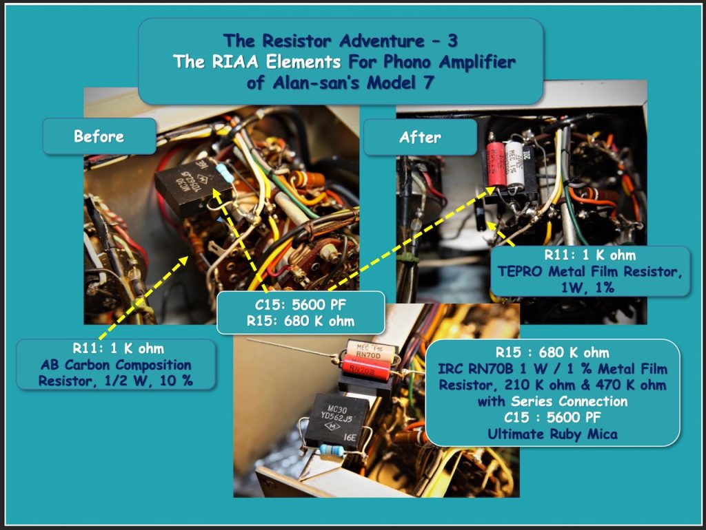
Well, R15, 680 K ohm, which is an element resistor of RIAA, has already been replaced with a metal film resistor in the first modification, but this time I replaced again with two old IRC resistors, 470 K ohm and 210 K ohm, connected in series.
This is also an example that is possible because of the metal film resistor, which has a high precision tolerance of 1%, and, of course, it also contributes to the extremely accurate RIAA deviation as designed.