Greetings friends, I hope you are well! 🙂
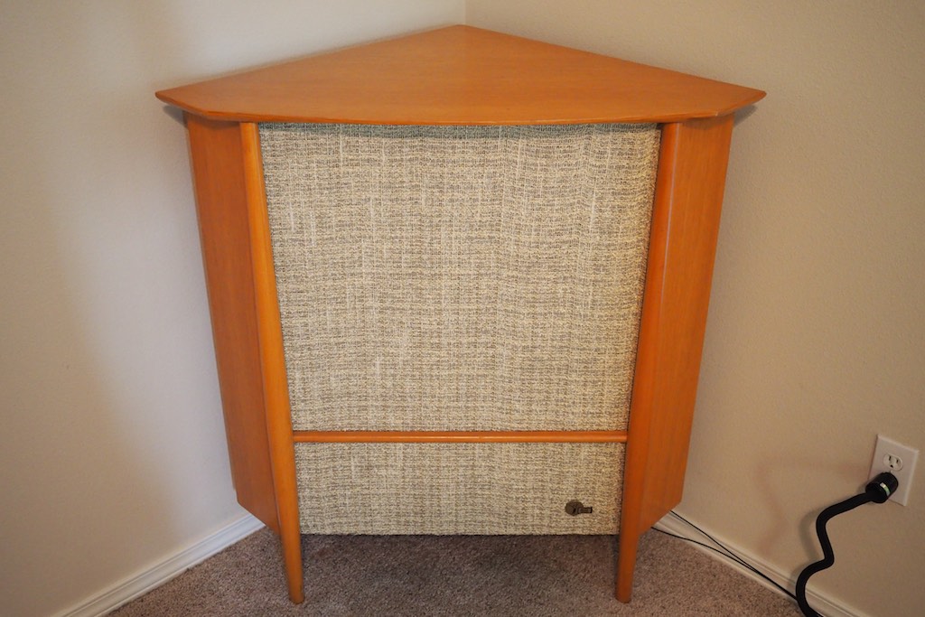
Vintage Altec 832A Corona loudspeaker in a room corner.
As a refresher, The Duelund-Corona 832A Project is about building new high-performance crossovers for my beloved vintage Altec 832A Corona loudspeakers (above) using the state-of-art Duelund CAST inductors and capacitors (below).
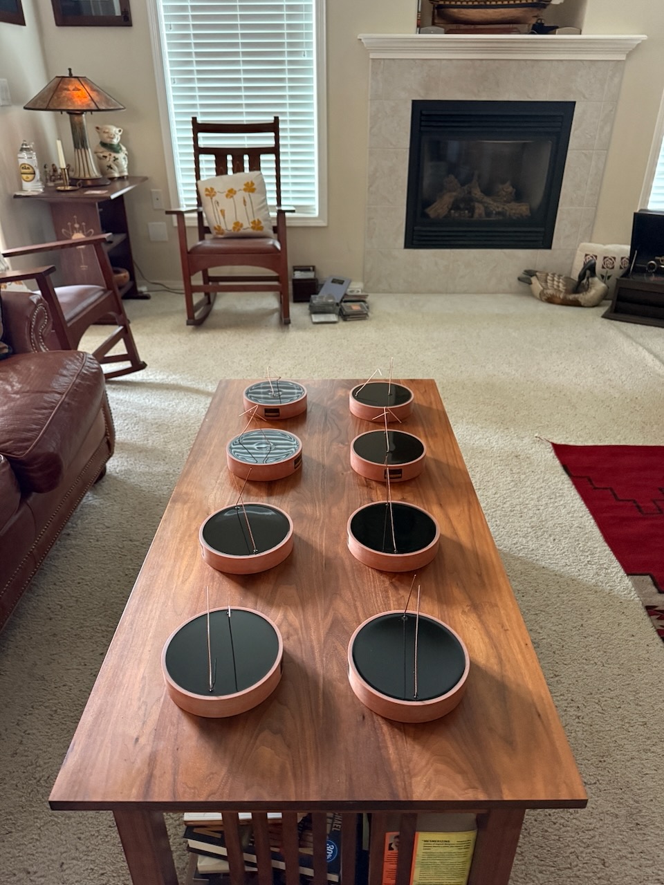
Duelund CAST copper 3.5 mH inductors and 10.5 uF capacitors for the project.
In particular, I'm building replacements for the stock Altec N800E crossover - or "dividing network" - as Altec would say, as used in the Coronas.
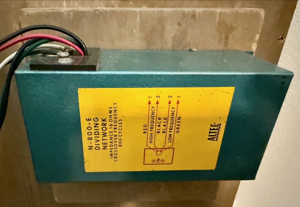
Altec N800E crossover.
Like all vintage Altec crossovers, the N800E crossovers include an incredibly useful feature borrowed from their professional Voice of the Theatre product line of loudspeakers, the ability to attenuate high-frequency output by various amounts.
That feature makes it possible to adjust the dB outputs of the high-frequency 16Ω Altec 802D compression drivers to match the dB outputs of the 16Ω Altec 803A low-frequency drivers, for different rooms or ears, as the case may be.
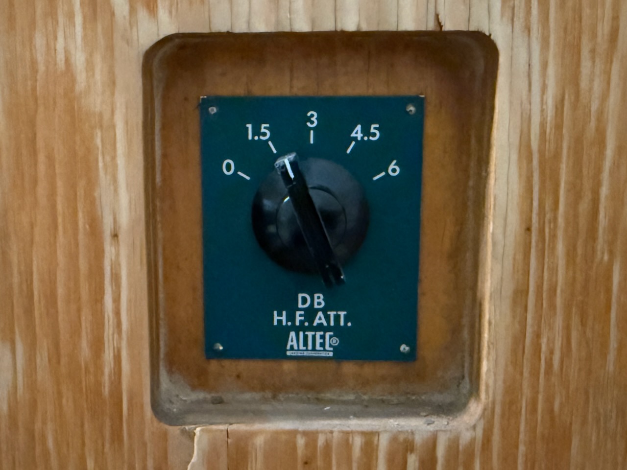
Altec HF adjustment.
On the other side of the N800E crossover you can see the attenuation choices: 0 dB, 1.5 dB, 3 dB, 4.5 dB, and 6 dB.
In the room that I have my Coronas in, I typically use 1.5 dB to 3 dB of attenuation - depending on the amplifier used - to balance the LF & HF dB output.
I really want to maintain the adjustability feature, so what does that mean for modifying the high-frequency circuit of the N800E crossovers I want to build?
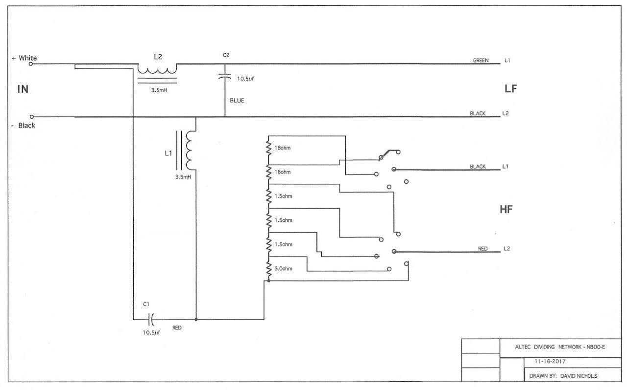
N800E crossover schematic courtesy of Great Plains Audio.
When I first looked at the N800E schematic I thought I could just replace the entire HF resistive network with an L-pad or autoformer to maintain the adjustability of HF attenuation I desired.
Then I began to doubt that, wondering if there should be some sort of resistance network in front of the L-pad/autoformer.
I was confused about what to do, so I contacted Pete Riggle (Pete Riggle Audio Engineering) to see if he could advise me. Pete builds lots of crossovers for vintage Altec owners, but the N800E crossover was a new one for Pete, so he did a little computer modeling to figure out options for a path forward.
Pete told me, "I simulated the E circuit (Corona speaker) crossover and found the crossover point to be 831 Hz with a 5 dB response bump centered at the crossover point. The perceived bump would be about 2 dB because the pressure waves from the woofer and tweeter do not combine in a correlated way."
Pete also simulated the values of various resistors that could be used with an L-pad in the circuit, and the overall attenuation they would provide.
When Pete looked over his simulation results, he told me "This implies that an L-pad could be used without a resistor network to provide attenuation up to 5.6 dB."
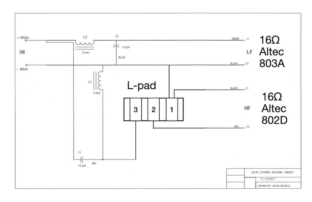
Altec N800E crossover with L-pad replacing the HF resistive network.
5.6 dB is almost exactly the range of attenuation the N800E circuit provides, of 0 db to 6 dB, so I really like the idea of being able to simplify the HF resistive circuit just by replacing it with an L-pad.So above is the modified N800E circuit with an L-pad replacing the resistive network.
A big "Thank you!" to Pete Riggle for his guidance on this question. Also, for those of you who want to do a crossover project but don't feel comfortable building it yourself, Pete can build it for you. You can contact Pete HERE.
So now I can go ahead and breadboard the crossovers. I still have to order a few miscellaneous parts to lay out the breadboards, dismantle my Corona loudspeakers and rewire them internally for the new crossovers, and so it will take me a while to get all that done so I can test the breadboarded crossovers.
Also, there are a couple of other attenuation options for the HF circuit I am considering trying in addition to the L-pads, and if I try them, then I can tell you about the sound quality differences between them.
The main question is will they be as easy to implement as an L-pad, or will I have to introduce other resistive elements to the HF circuit?
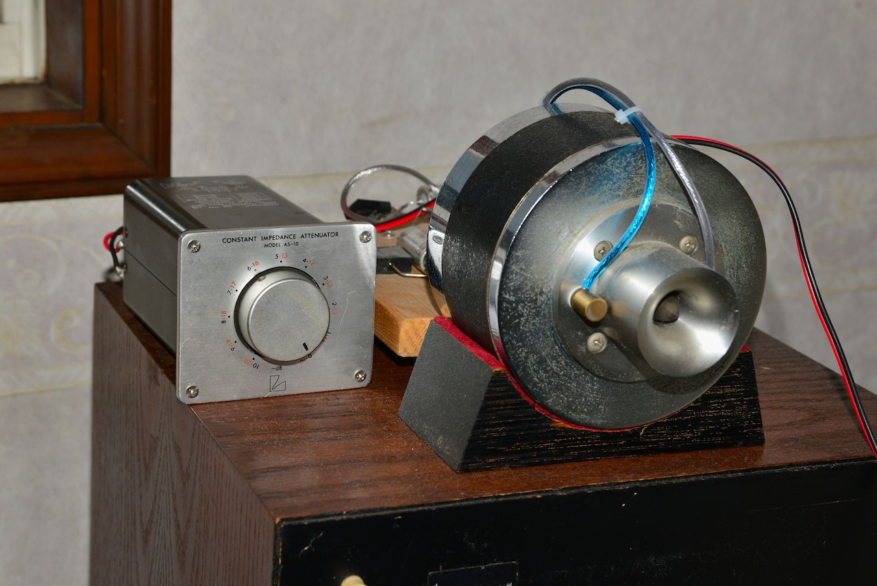
LUXMAN AS-10 transformer constant impedance attenuators.
Friend Yazaki-san sent me a message saying, " I just received a pair of used LUXMAN AS-10 transformer constant impedance attenuators. I will study them in the future, as I'd like to investigate the differences in characteristics and sound quality between the resistor type and this transformer type. In fact, I recently heard from my friend Kajiwara-san that he actually replaced his resistor type attenuator with this AS-10 and got the best results, so I'm looking forward to this experiment."
Or another possibility is using Dave Slagle's autoformer modules, which are also supposed to be better sounding HF attenuators than L-pads.
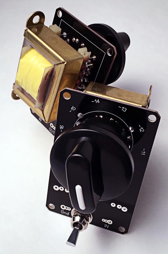
Dave Slagle's "Speakerformers".
So the path forward is to breadboard the crossovers with L-pads and test them to make sure the circuit works as intended.
If the result sounds fantastic I may just stop there ... or curiosity may bet the better of me and I may want to try a pair of Luxman AS-10s or Dave's Speakerformers.
After all that is completed, then I can focus on transferring the breadboard design to an external crossover enclosure, or alternatively, to mount them inside the loudspeakers.
Stay tuned, much more to come!
As always, thanks for stopping by, and may the tone be with you!
Previous Articles In This Series
- A new audio DIY project announcement: The Duelund-Corona 832A Project! HERE.
- Today's Fresh Catch: Capacitors & Inductors for the Duelund-Corona 832A Project! HERE.